
by Zhigang Liang, Renesas Electronics America
The USB-C interface is revolutionizing the way we connect our electronics devices. Thanks to high-speed data transfer and high power delivery, USB-C port adoption is accelerating, and the USB Power Delivery (PD) 3.0 and USB-C specifications are maturing. While consumer electronics OEMs move fast implementing USB Type-C as their standard power and data connection, there still are challenges ahead. This article discusses how Fast Role Swap (FRS), a new function defined in the latest USB PD version 3.0 specification, affects mobile computing power design.
What is Fast Role Swap (FRS)?
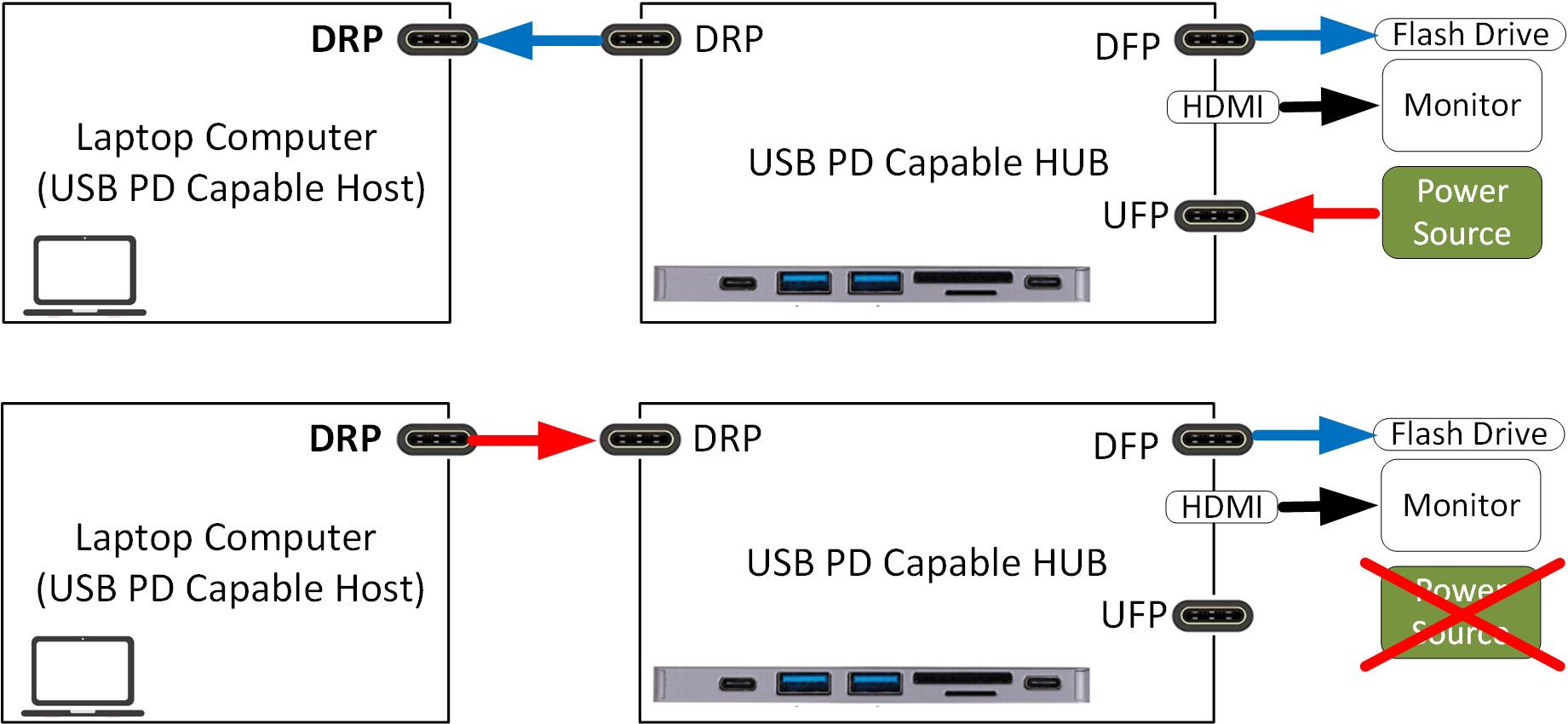
FRS aims to prevent the USB PD Capable Hub and all its buck-powered accessories from encountering a data communication interruption when the Hub upstream facing port (UFP) stops sourcing power. In a typical setup, a laptop computer and LCD monitor connect to the USB Hub as shown in Figure 1 (top diagram). The power source adapter connects to the USB Hub and powers the Hub until an FRS occurs. The USB PD Hub is sourcing power to USB devices (e.g., flash drive) and the USB PD Host laptop computer is sinking power.
Figure 1 (bottom diagram) shows the system power flow after removing the power source. In this case, the USB PD Hub recognizes it has lost power and sends an FRS signal over the configuration channel (CC) line from Hub dual role port (DRP) to the host DRP. The USB PD Host monitors the CC line and detects the FRS signal. The USB PD Host changes its power role from Sink to Source and the Hub DRP starts sinking power. The USB accessory flash drive and monitor continue functioning during the FRS event, not noticing the removal of the previous power source.
FRS adds new challenges to power design
FRS is easy to understand, however, meeting the FRS spec is not easy. The major challenges are twofold:
- The timing requirement, defined as parameter tSrcFRSwap, must be less than 150us. This is the time from Vbus dropping below vSafe5V until the new Source supplies USB Type-C current.
- Various scenarios depend on whether the Vbus voltage level is higher than vSafe5V or at vSafe5V. If the old Vbus voltage is higher than vSafe5V, the new source waits until Vbus decays to the vSafe5V window and then starts Vbus voltage regulation, staying within the vSafe5V specification. Alternatively, if the old Vbus voltage is 5.0V, the new source must start regulating Vbus after receiving the FRS signal. The lack of the new source buffer time makes this challenging.
FRS in mobile computing
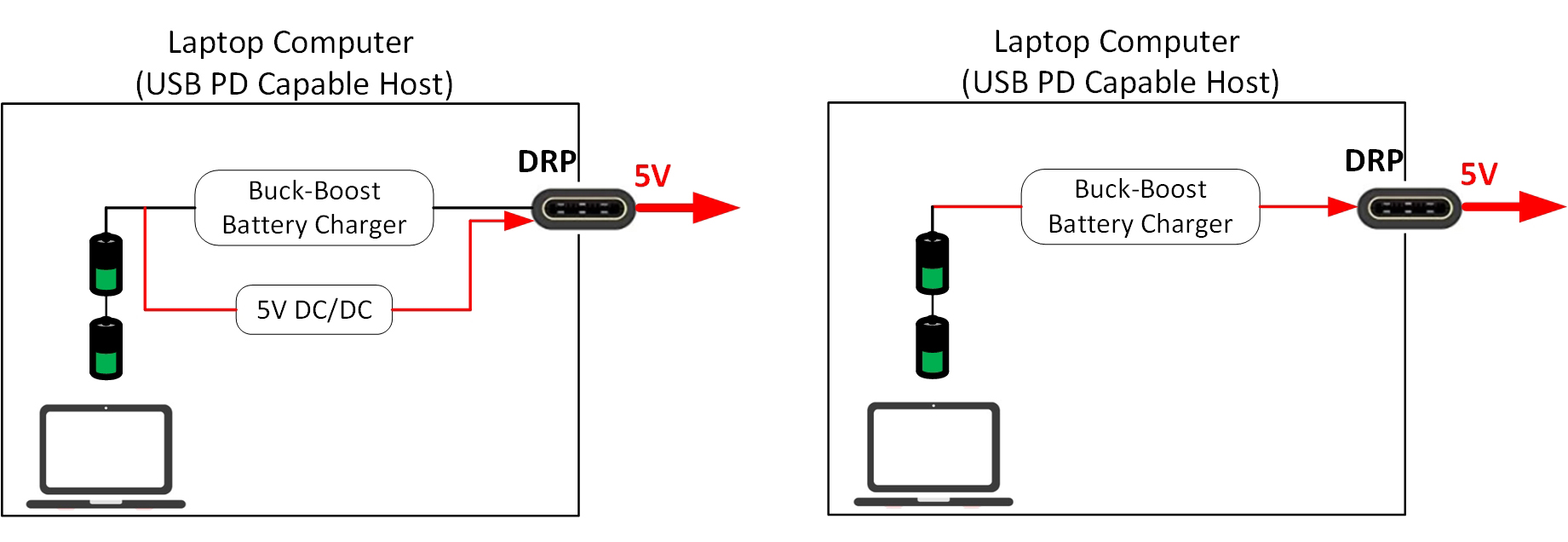
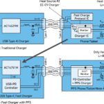
Laptop computers use a USB PD controller at each USB-C port to detect the FRS signal and notify the embedded controller (EC). Figure 2 (left) shows a typical power solution for FRS. After an FRS event is detected, the buck-boost charger stops operation by entering battery-only mode. Meanwhile, the 5V DC/DC converter is enabled with its input from battery pack and its Vout is diverted to the DRP port to hold Vbus to vSafe5V. This solution might need an additional 5V DC/DC converter and power path controls to route battery power through 5V DC/DC to the DRP.
Figure 2 (right) shows a new solution that operates the buck-boost battery charger in reverse operation to regulate Vbus at vSafe5V. The battery charger is able to operate in forward and reverse operation due to its symmetrical architecture. Compared to the typical solution (left), the new solution (right) eliminates the 5V DC/DC converter, including power path selector and switches. Most importantly, the buck-boost charger’s fast control loop transition changes its operation direction from forward to reverse in 150us, including EC and battery charger communication. Additionally, the new solution provides USB On-The-Go (OTG) full 5V – 20V seamlessly after a FRS event, while the typical solution cannot.
USB PD 3.0’s FRS function enables uninterrupted power transfer and continuous system operation. FRS enhances the goal of USB Type-C, which is to provide a flexible connection interface supporting DC power delivery and high-speed data transfer. Mobile computing devices can utilize a buck-boost battery charger to support FRS events without additional DC/DC or power path while meeting the USB Type-C specification requirements.
About the Author
 Zhigang Liang is technical marketing manager for battery charger products with the Battery & Optical Systems Division at Renesas Electronics America. Mr. Liang holds a Ph.D. in Electrical Engineering from North Carolina State University.


Leave a Reply