Keeping components and systems cool enough and within their safe temperature zone is a concern for many, though not all, designers and projects. Excessive heat as measured by temperature can cause erratic behavior, inaccuracy and drift due to temperature coefficient-induced shifts, shortened component lifetime, and even outright failure.
Q: What are the cooling options?
The cooling world divides into passive- and active-cooling regimes. In passive cooling, sometimes called “unforced air” cooling (although cooling does not necessarily have to involve air) no power is expended in the cooling process. In active cooling, often called “forced air” cooling (again, somewhat of a misnomer), an additional powered component such as a fan, refrigerator, or pump is needed to drive the cooling function.
Q: Why is passive cooling an attractive option for cooling?
Passive cooling can be simple, low cost (no added fans or similar components), reliable (nothing to wear out or break), and straightforward to analyze.
Q: Why is active cooling sometimes required, rather than passive cooling?
In many cases, the passive arrangement simply cannot supply the necessary amount of cooling capacity solely through unforced airflow or other passive heat-flow approaches.
Q: How is heat removed from a circuit of a system?
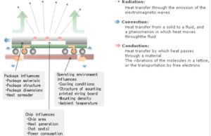
The laws of physics define three ways heat is moved:
- radiation, as infrared electromagnetic waves. An incandescent bulb, for example, radiates its heat to its surroundings. For most electronic systems, such radiation is not a significant part of the cooling possibilities; however, for spacecraft or systems functioning where the air is thin, radiation becomes the dominant “final step” cooling mechanism.
- conduction, where the heat flows through a solid material, usually one with low impedance to heat flow such as copper, or aluminum;
- convection, where the heat is carried away by a fluid such as air (in most cases), or a liquid such as water or a Freon-like fluid.

Q: What is the first question to ask when setting up a passive-cooling strategy?
The question is simple: to where will this undesired heat be going? The laws of thermodynamics are clear: absent some sort of active heat-pumping mechanism, heat can only flow from a warmer area to a cooler one. This, when engineers speak about using passive cooling to get heat “away”, the question is “where is this ‘cooler’ away place to which the heat will flow?” If there is no cooler area for the heat to reach, then passive cooling will not work.
Q: What is a second critical question for cooling strategy?
The second question concerns the nature of the excessive heat source. Is the source problem highly localized, such as due to a single component, while the rest of the system enclosure is cool enough? Or is the overall system too warm, from the cumulative effect of the many components within? In the first case, the heat need only be removed from the local area and can be spread into the larger system; in the second case, the heat of the entire system must somehow be moved elsewhere.
Q: What is a third critical passive-cooling question?
Even if there is a cooler area nearby to which the heat can be transferred via conduction and convection, will this added heat (once transferred to this zone) make it or its components too hot, to the point where it no longer can act as a cool reservoir? For example, if the copper layers of the PC board are used to draw heat away from a hot IC, will that resultant heat then be too much for the nearby components which are now subject to that additional heat?
Part 2 will look at specific passive-cooling issues in more detail.
References
Infineon Technologies, “Thermal Resistance Theory and Practice”
Infineon Technologies, “Thermal Modeling of Power-electronic Systems”
Renesas Electronics Corp,, “Heat-dissipation mechanism”


[…] Part 1 looked at the basics of passive cooling. Part 2 explores the specifics of passive cooling in more detail. […]