
LEDs – light-emitting diodes – have largely supplanted other sources of light in many applications. They are used in applications ranging from small on/off power indicators, to small and large alphanumeric displays, to screen backlighting, and even for area and street illumination.
It’s well known that LEDs are far more efficient than venerable incandescent lighting, and somewhat more efficient than fluorescent-based sources. While there are still specialty areas better served by non-LED sources, these are a smaller portion of the application arena with each passing year. LEDs are available in a wide array of colors including green, yellow, blue, red, and the very important “white” (there is no single “white” color as it has many renditions).
What type of power source do LEDs require?
Unlike incandescent sources which are resistive loads and need to be driven by a voltage source, LEDs are current-driven, non-linear loads. The current needed by most LEDs is between typically 15 and 30 mA, although high-brightness LEDs (HBLEDs) may operate at 50 mA or more. As they are diodes, there is a forward-voltage drop of about 1.8 to 2 V across each LED (for red) and 4 V (for blue), which factors into drive-current/voltage analysis.
What happens if you drive an LED from a voltage source?
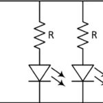
It is possible to drive an LED from a voltage source, using a current-limiting resistor to keep the current at the desired value, Figure 1. This is inexpensive and viable for simple applications such a driving a basic power on/off indicator light.

But this approach has several drawbacks: the current and thus LED brightness will vary with the supply rail voltage; even if the voltage is regulated and constant, the brightness will vary as each LED has a different voltage drop and thus current flow. Also, it is inefficient, as the current-limiting resistor dissipates power.
What’s the better way to drive an LED?
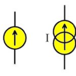
The more effective way to is to use a current source rather than a voltage source. A current source is analogous to a voltage source, except that it regulates the output current, rather than the voltage, to a fixed value regardless of the load (within limits, of course). A current source is no more difficult to build than a voltage source (if you decide to go the “make” route); of course, many standard current-source ICs and modules are also available (for the “buy” route).
The current level is selected or set to provide the value that the specific type of LED being requires for the intended level of output brightness. No resistor is needed and there is no inefficiency other than within in the current source itself, which typically has efficiency between 75% and 90%.
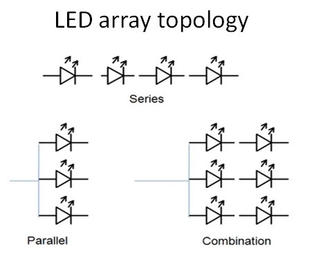
What are the arrangement topologies when using multiple LEDs? Three topologies are possible: series only, parallel only, and combined series/parallel, Figure 2.
Each approach has unique advantages and disadvantages:
For the series-only topology:
requires only a single current source;
has simple interconnect wiring;
the short-circuit failure of any diode affects only that diode, and the rest of the string functions properly and still sees the specified drive current;
open-circuit failure of any diode disables the entire string (note: special components are available which can be wired in parallel with each LED, and is normally an open circuit. However, if the LED fails as an open circuit, this component turns “on” and becomes a bypass path around the open LED, thus allowing the rest of the LEDs to stay on);
it requires attention to required source-compliance voltage, which is the sum of all the diode drops in the series string. For example, if there are ten diodes with a 1.8 V drop for each, the current source must be able to source the current at a compliance voltage of 18 V (actually, about 2 V higher, due to other factors). Reaching this compliance voltage means that the DC voltage-supply rail for the current source must have at least this value;
is wiring-intensive when the diodes are located in difference sections of the design layout.
For the parallel-only topology:
the current from the single current source does not divide “evenly” among the LED strings due to differences among individual diodes, so each LED will see a different current and thus LED brightness;
for an open-circuit failure of any LED, the other diodes will continue to function, but the current to each will increase; in some cases, the resulting current will exceed a LED’s maximum rating;
short-circuit failure of any diode results in all other LEDs getting zero current and thus being dark. Unless the current source is protected against short-circuit loads (most are), it may be damaged. Some designs use a small resistor in series with each LED to prevent a diode short circuit from affecting other diodes, but this degrades the current-sourcing consistency to each diode).
is advantageous when the LEDs are physically located at a distance from each other.
The combined series/parallel topology combines the attributes, both pro and con, of the series-only and parallel-only approaches. The optimum arrangement of many LEDs to use in each series string and how many such strings to use in any given application is a function of the number of LEDs, impact of LED failures, available compliance voltage, LED brightness/color matching at a specified current, and physical-layout considerations. Many designs use the hybrid approach with a separate current source for each series string, which overcomes many of the weaknesses but at a “cost” of needing more such sources.
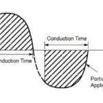
Part 2 will look at dimming LEDs, an important topic as LEDs are increasingly being used for area illumination and light fixtures.

Leave a Reply