
Peer-to-peer, engineer-to-engineer questions and answers from the EDABoard.com engineering community around power electronics. Click the “Read more” link and follow the entire conversation and maybe add your two cents by logging in to EDAboard.com
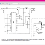
Extremely simple overnight AAA Ni-MH charger – I want to build an ultra simple charger, to charge a 750mAh 1.2V AAA Ni-MH battery. The charger must be very simple, but it has to have a series diode, because it is needed for my circuit, so as to prevent reverse power flow. Read more
440V 3phase to 0-17V/1000A rectifier design – Which will be good using six pulses and a 6SCR or using an old magnetic reactor plus diodes? If six pulses is good, then how to generate 30-degree crossing of 3-phase line as switching is done after 30 degrees of each phase. Read more
Lots of failing outdoor LED lamps – We have installed one hundred 25W outdoor LED lamps in a town in Bosnia. Sixty failed in just a few weeks. They all are fed from a single 240VAC generator which delivers power to the 2500 meters of mains cable. A contactor near the generator is used to switch them all on/off. The lamps are fitted every 25 meters along this cable. The cable is overhead (not buried). It’s aluminum cable. Its twisted, though the installers tell us that in places the twisting is “not so tight”. We suspect there is an awful lot of mains stray wiring inductance. Read more
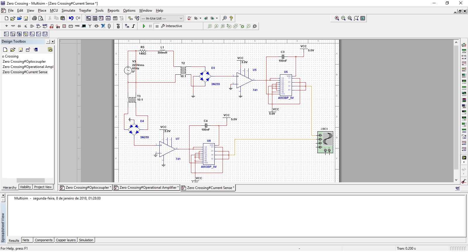
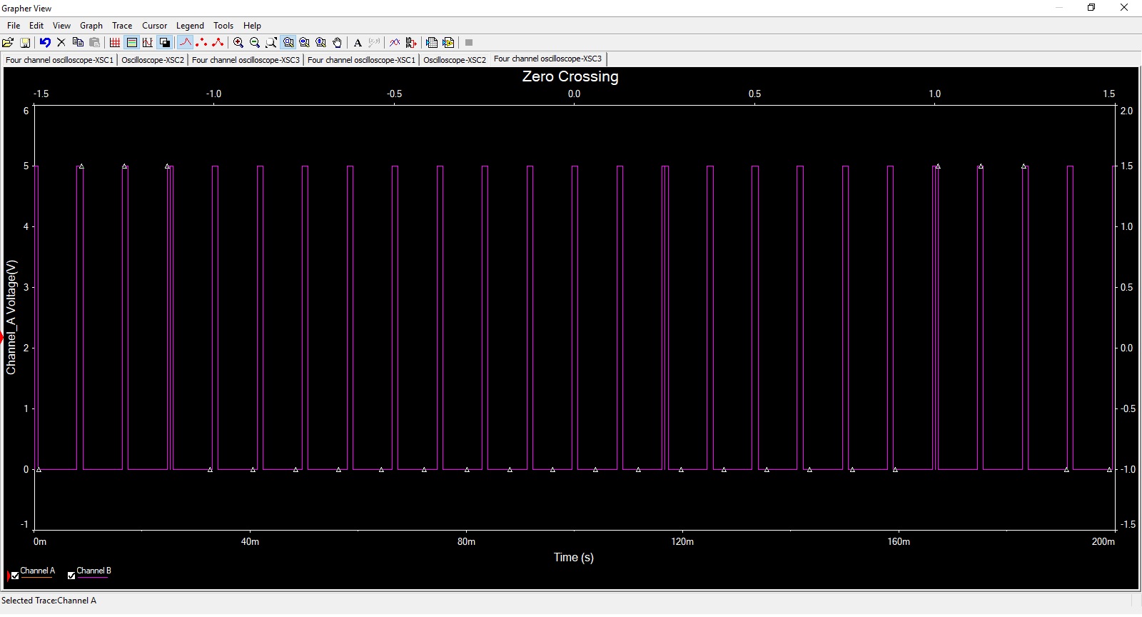
Power factor using zero crossing – I’m trying to do a power factor measurement for academic work. I’m using the zero crossing detection on the voltage and the current so that I can do the difference between then and convert to angle. Using the op-amp 741 as a voltage comparator I’m not able to get the phase wave of the current. Read more
Digital peak current mode control – I am new to chip design and peak current mode control, I have a project where I am asked to design a digital peak current mode control of boost converter and implement it on ASIC. If you have any good references where i can learn to design such hardware share it with me. Read more
High power 440 KHz oscillator design – I want to design an oscillator running at 440 Khz to experiment with an inductive coupling circuit I have. Basically I have a small coil that resonates at 440 Khz and I want to drive a much larger coil with this frequency to see if I can increase the coupling distance to around 6 inches everywhere inside the larger coils diameter. I don’t know what current I will need but I’d like to try up to 1A as a start. Read more
Lowest RDS(on) MOSFET available – I have an application in which I must switch very high currents through a coil, at low voltage (<10V), with an n channel MOSFET and I need the absolute lowest RDS(on) commercially available, other criteria are irrelevant. So far I found IPT004N03 with 370µΩ, typical. Do you have any recommendation, is out there a lower RDS(on) available? Read more
Rectifier with Schottky diode or PN junction diode? – I want to make a small variable regulated PSU using a 13.5Vac/1.6A transformer and a low dropout voltage regulator LM2941. My question is should I use shottky diodes or pn junction as full wave rectifier? i want to use Shottky because of their low forward voltage.Will the higher reverse leakage current of the Shottkys be a problem? I have four SR2100 Shottky diodes and a W06G bridge rectifier.
Calculate impedance manually – from data samples – Basic calculating of load impedance is fairly easy when familiar to complex numbers as same formulas is used as for a resistive load with no inductive or capacitive elements. But I want help regarding how to calculate momentary value of load impedance when there is a set of measured samples of voltage and current. Read more
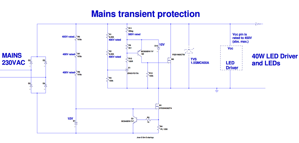
Mains transient protection circuit looks very bad – Our contractor has put forward a Mains Transient protection circuit (for our power factor corrected 40W offline LED driver) which looks so disastrous that please may I put it here for judgement? (it is as attached). The idea is that any transient gets shunted by both the TVS and the controlled NFET , M3. The Current clamp based around M1 ends up taking some of the transient voltage, so that the LED driver and LEDs don’t get exposed to the transient overvoltage spike. Read more
Leave a Reply