
Peer-to-peer, engineer-to-engineer questions and answers from the EDABoard.com engineering community around power electronics. Click the “Read more” link and follow the entire conversation and maybe add your two cents by logging in to EDAboard.com
Gas discharge tube based mains transient protector – We have designed a 40W non-isolated, offline, 230VAC LED lamp. For transient protection, we have a 470V gas discharge tube (Bourns, 2051-47-SM-RP-LF) in series with a 270V “surge absorber” (Panasonic, ERZVF2M271). This transient “block” sits across live and neutral, just downstream of the fuse. The fuse is the first thing after the mains input connector. Our contractor tells us that because the Gas Discharge Tube will always fail open circuit, we should, therefore, move the fuse downstream of the Gas discharge tube based transient protector. This way, when the gas discharge tube flashes over due to a transient, the fuse will not blow, and so the product will stay functional for longer. Do you agree? Should we do this? Read more
Wrong bulk cap formula – Calculating the bulk cap of a “C” filter for a full bridge rectifier (see picture), I get the conduction time “tc” as follows:
tc=arccos(Vmin/Vmax)/(2Πf)
Knowing that sin(Π/2-β)=cos(β), one gets the following:
tc=1/(4*f) – arcsin(Vmin/Vmax)/(2*Π*f)
Now inserting the above expression for “tc” which involves the “arcsin”, one gets almost the same expression as at page 25, equation 3 of the TI’s datasheet. Using my calculations, I get 1/2Π * arcsin(Vmin/Vmax) while TI is showing 1/Π * arcsin(..). They are dividing by “pi” only. Did I make any mistake? Read more
SiC intrinsic body diode vs external body diode – I am planning to use sic MOSFETs in inverter application(2 level or 3 level), and I searched some manufacturer and prices, I saw sct30n120 and ST says ‘ Very fast and robust intrinsic body diode (no need for external freewheeling diode, thus more compact systems)’ , does intrinsic body diode can handle the current as much as the MOSFET? Let’s say 25A current, or should I use external body diode? If I use external body diode; can I use fast recovery diode instead of SiC SBD ? What will be the disadvantages of that. Reverse recovery? Read more
Series string of inductors for use as an inductor in an SMPS – Regarding using inductors in series for an SMPS power inductor…Post #3 of this thread…..
http://www.edaboard.com/thread295809.html
says….”One possible problem with series inductors is the midpoint ringing a lot due to the self resonance of the inductors. If this is a problem then damping it with a RC snubber network may be necessary.” Surely a single inductor would have stray capacitance too?….so is the ringing really a particular problem for series inductor chains? Read more
Problem facing while multiple circuits are connected after bridges – I have attached my circuit here where I am not able to understand why the circuit is behaving like this:
 Separately all circuits are working fine, but by integrating all this, I am facing a problem. Can someone have a clue which is the right approach to the correct circuit? Read more
Lead acid battery charging circuit for 24V – I have to charge a 24V 12Ah Lead Acid battery with combination of two 12V batteries in series. I have selected UC3906 charging IC for to charge the battery. I gone through the application note of UC3906 in that they had given, there is a three state of charging. Bulk Charge State, Over State, Float state.
I have constructed this circuit to charge the battery. This circuit battery is getting a charge, but I couldn’t identify the state of the charge. Read more
Problem of surge currents flowing in the sense resistor of LT1248 and LT1249 PFCs – The LT1249 and LT1248 are both CCM PFC controllers. They are very similar chips.
Why is it that the LT1249 datasheet, on page 10, recommends a surge current bypass circuit (three diodes) for the sense resistor, but the LT1248 makes no mention of any need to protect from such surge currents? (eg the rush of current through the sense resistor if the PFC is switched on at Mains peak). Also, The LT1248 leaves one with a choice of what maximum sense resistor voltage to employ…but what is the maximum? Read more
Inrush current limiter+Bias PSU for mains powered ZVT – Can anyone help me understand the following:
1) Regardless of any regulation about power factor, is it any other issue I do not see in powering the ZVT converter directly from the AC mains?
2) Can anyone recommend how a Bias PSU can be derived in such a converter derived from the AC mains?Read more
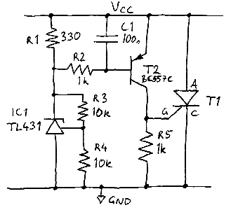
Can I replace SCR with power MOSFET? – Is it possible to replace the SCR of the attached crowbar circuit with an N-channel power MOSFET? I have no power SCRs but have some power N-MOSFET transistors. Read more
 Gate drive transformer does not state max leakage inductance – Do you know why this gate drive transformer family (HM42) states the minimum leakage inductance instead of the maximum?……as you know, the minimum figure is not useful….customers need the maximum, so as to calculate the delay in turning on the FET. If you are also stumped, then please may you tell of a different family of OTS FET pulse transformer drivers?, which do state max leakage…F(sw) is 100 kHz, so we need low leakage. Read more
Leave a Reply