With the rise of green energy and transportation technologies, power factor correction (PFC) is growing in importance. PFC is an integral aspect of green energy designs since it can improve energy efficiency. PFC topologies can be passive, partial switching, or active, depending on system requirements. The appearance of wide bandgap power semiconductors combined with advanced digital control techniques enables new PFC topologies that combine higher efficiencies and lower costs. This FAQ begins by reviewing basic power factor concepts, then looks at how to implement PFC using passive and active techniques for single-phase systems and active PFC topologies for three-phase systems.
Power factor (PF) is defined as the ratio of real power (Watts = instantaneous V x I) to apparent power (VA = V(RMS) x I), but it’s not quite that simple. This simple definition only applies to sinusoidal waveforms. Plus, PF can be lagging or leading (Figure 1). Inductive loads are lagging (current lags voltage), and capacitive loads are leading (current leads voltage).
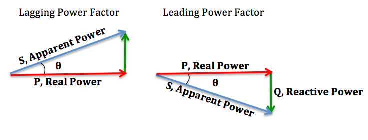
When the current waveform is not sinusoidal, as is the case for switching power converters, the PF can also be less than unity, but it’s more complex. The current in a switching power converter contains frequency elements that are multiples of the switching frequency. That results in what’s called ‘distortion power factor.’ Distortion power factor measures how much the average power transferred to the load decreases due to the harmonic distortion to the load current. High power and total harmonic distortion (THD) are directly related. As a result, international power quality regulations specify PF and THD levels. For example, IEC 61000-3-2 limits mains voltage distortion by specifying the maximum value for harmonic currents from the second harmonic to the 40th harmonic current.
PFC can be implemented using passive (or static), partial-switching, and active (switching) techniques. Passive PFC simply inserts an inductor (also called a reactor) in series with the power supply. The need to use a line-frequency (therefore large and expensive) inductor limits the use of passive PFC to low-power applications. Partial-switching PFC is often used with a voltage doubler rectifier in home appliances such as small inverter air conditioners. Active PFC is the most common implementation and delivers high PF, compact implementations, and high efficiencies. Active PFC can support single-phase and three-phase systems.
Passive PFC
The inductor (L) helps improve the PF in a voltage doubler rectifier, but it’s still not ideal (Figure 2). Current is only flowing during part of the AC cycle. Because this PFC circuit operates at a mains frequency (50 or 60 Hz), it requires a large inductor and is limited in the power level it can handle. Performance can be improved by adding a switching element following the inductor.

The switching element in a partial switching PFC can switch several times during each cycle, significantly improving input current flow compared with a passive PFC solution (Figure 3). But there is still a significant input current distortion compared with the ideal case. A partial switching PFC turns the switch on when no current is flowing. In addition, since the inductor stores energy, this design can boost the output voltage enabling more efficient operation of the rectifier section. Switching losses are relatively low since the switching frequency is a low multiple of the mains frequency.

Single-phase active PFC
A common topology for single-phase active PFC is a controlled boost converter (CBC) converter where the switching element is on the DC side of the rectification stage (Figure 4). By controlling the AC current to be sinusoidal and in phase with the input voltage, CBCs perform DC voltage regulation and present a resistive load to the mains input. Based on the circuit topology, CBC converters can be classified as bridge boost converters (BBC), semi-bridgeless boost converters (SBBC), and bridgeless boost converters (BLBC). The ‘best’ topology selection involves tradeoffs between power handling capability, efficiency, complexity, THD requirements, and other performance considerations.

BBC topologies can provide high PF and low THD, but there are other tradeoffs:
- At least three semiconductor devices are in the current path from the source to load, increasing conduction losses.
- To meet IEC 1000-3-2 THD requirements, a BBC design often requires a switching frequency greater than 30kHz, reducing the utility of the topology in higher power applications. BBC is generally only useful up to a maximum of 1 kW.
- Care must be taken to ensure that the inductor core does not go into saturation.
SBBC designs are a variation on the BBC approach but is based on a half-bridge topology and include a different set of design and performance tradeoffs:
- SBBC has only two semiconductor devices in the current path, compared with three for the BBC, reducing conduction losses.
- SBBC designs require more passive components, including an additional inductor on the input side, plus additional diodes, capacitors, and inductors to help control EMI concerns.
- SBBC PFC can handle higher power levels compared with BBC designs.
BLBC PFC designs replace the rectifier bridge with switches or have an asymmetrical arrangement of their elements in the converter branches which mitigates reverse-recovery currents from diodes. Tradeoffs include:
- There is no common-mode interference concern since the output voltage is clamped during each half cycle to the input by the diodes.
- Some BLBC PFC designs can be used for bidirectional power conversion, that is not possible with BBC, or SBBC approaches.
- Control and isolation are more complex and can lead to higher costs.
Interleaving two or more individual PFC converters can provide another path toward improved performance. For example, interleaving two PFC converters, each operating 180° out of phase, reduces the high-frequency ripple components of the input current and the current into the output capacitor. That enables the use of smaller inductors, smaller input capacitors to control EMI, and the need for a smaller PFC output capacitor, all of which can contribute to lower costs and more compact designs. Compared to a single-phase PFC stage of equal power, the reduced ripple on the input current means designers can use smaller input capacitors and reduced EMI filtering. In addition, reduced high-frequency ripple current into the PFC output capacitor means designers can reduce its size and cost.
Three-phase PFC
Three-phase PFC topologies involve compromises between the number of semiconductor devices and the voltage ratings of the devices. Most three-phase PFC topologies benefit from the use of digital control. Some of the more common topologies include the following:
Vienna rectifier – This topology uses three switches but needs eighteen diodes, six diodes per phase (Figure 5). The switches and diodes are all 600-V or 650-V devices. Since no 1200-V rated devices are used, losses are reduced. On the other hand, there are two high-frequency diodes in series in the current path, which reduces efficiency. For those diodes, it’s a compromise between voltage drop and reverse recovery.
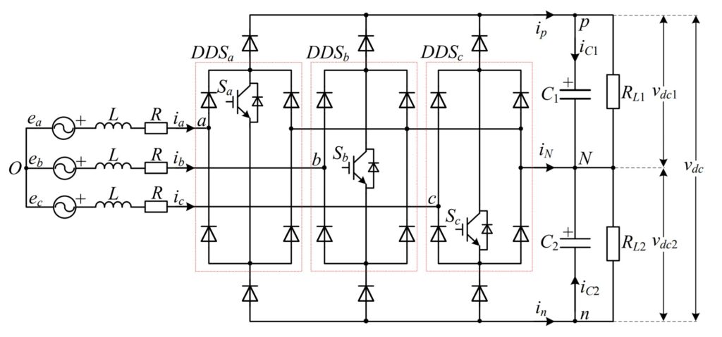
T-neutral point clamp (T-NPC) boost – Compared to the Vienna rectifier, the T-NPC uses back-to-back switches. The switches are 600-V or 650-V rated, but the diodes are 1200-V rated. The number of components is lower compared with a Vienna PFC. The conduction losses are lower since only one diode is in series with the current flow at any point in time. But the need to use 1200-V diodes increases the switching losses, possibly adding to thermal management considerations. T-NPC converters generally offer slightly better efficiency compared with Vienna rectifiers, and a T-NPC converter can be used to implement a bidirectional PFC if the diodes are replaced with switches.
Neutral point clamp (NPC) and active-neutral point clamp (A-NPC) boost – The NPC topology uses six IGBTs and twelve diodes, all rated 600-V or 650-V. Substituting switches for the diodes results in a bidirectional topology called an A-NPC boost. The lack of 1200-V devices reduces loss, but the need to have two components in series in the current path increases losses, complicating thermal management. As a result, the NPC topology has higher conduction losses than the T-NPC.
Six-switch boost – Performance is similar to the Vienna rectifier but with slightly higher efficiency, leading to higher power densities. In addition, the bidirectional operation is possible. In terms of efficiency, the fact that there is only one switch per phase somewhat compensates for the need to use 1200-V devices. Control can be less complex than other three-phase PFC topologies. In some applications, 900-V devices can replace the 1200-V devices, helping to reduce losses.
Three parallel single-phase with neutral – The use of three single-phase PFCs is in some ways simpler than using one of the three-phase PFCs described above. Single-phase PFCs do not need the digital controller usually required for a three-phase PFC. A neutral connection is necessary when using three single-phase stages, especially in unbalanced systems. While simple in concept, the neutral wire adds to system costs. This approach is limited to a few kilowatts of power.
Summary
PFC is an important aspect of maximizing the benefits of green energy and transportation technologies. Low PF causes inefficient power transmission networks and decreases power conversion efficiency. Waveform distortion can be caused by electronic power converters and is closely related to PF since both results in high levels of THD. PFC can be implemented using various techniques, including passive, switched, and active PFC for single-phase installations and various active three-phase PFC topologies for higher power installations. Each of the many PFC choices offers performance tradeoffs between efficiency, power density, and cost.
References
PFC Single-Phase AC/DC Boost Converters: Bridge, Semi-Bridgeless, and Bridgeless Topologies, MDPI
Power Factor, Wikipedia
Power Factor Correction (PFC) Circuit Basics, Texas Instruments
Power Factor Correction (PFC) Circuits, Toshiba Electronic Devices & Storage
Power Factor Correction (PFC) Handbook, ON Semiconductor





Leave a Reply