
The power management IC (PMIC) is often a vital part of the lower-voltage DC subsystem, as circuits have multiple power rails with tight individual specifications as well as mandated relationships among them.
Part 1 of this FAQ discussed the need for, PMICs and their general characteristics. Part 2 now looks at specific ICs which implement the PMIC functions.
Q: Who makes these PMICs?
A: Nearly every vendor of analog or power-related ICs makes them: Analog Devices/Linear Technology, Maxim Integrated, Texas Instruments, ST Microelectronics, NXP, ON Semiconductor/Fairchild, and others.
Q: If I don’t need a lot of PMIC functionality, what are my simper PMIC options?
A: Begin with a non-PMIC type of PMIC family such as the TPS621xx and TPS821xx families from Texas Instruments. These are single-output buck DC-DC converters with a wide input-voltage range from 3 V to 17 V and adjustable output voltage of 0.9 V to 6 V, to provide multiple rails to a system.
Q: Is that all they do?
A: No, they also include some basic PMIC functions which are “activated” via three additional pins for enabling (EN), power good (PG), and soft start/tracking (SS/TR). By connecting these pins in different ways among these ICs, it is possible to implement basic PMIC functions without a separate PMIC.
Q: For example?
A: For the sequential startup mode described in Figure 3 of Part 1, the ICs are connected as shown in Figure 1.
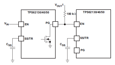
The PG pin of the first device enables the second device. When the first device’s output voltage reaches its nominal level after getting enabled, its own PG pin goes high, which enables the second device.
Q: Anything else?
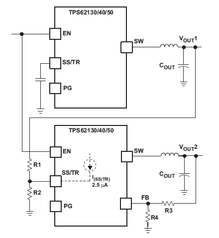
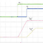
A: The same ICs can be used to provide the ratiometric timing shown in Figure 4 of part 1, see Figure 2:

In this arrangement, both output voltages start as soon as the enable pin goes high, and both voltages reach regulation at the same time. As the output voltages are not the same but their “soft start” times are equal, their slopes are different. (Note: the “soft start” circuit controls the output-voltage slope during start up.)
Q: How about the third PMIC sequence?
A: The ICs can also be arranged to provide the simultaneous start-up of Figure 5 of part 1 (Figure 3):
By using some basic equations related to the values for external passive components R1 and R2, as detailed in Reference 5, the slopes of both output voltages can be set and made equal, leading to both voltages reaching regulation at different times.
Q: This is all good, but I have many DC rails for my processor, and need more flexibility and functionality in a PMIC, so what can I use?
A: For these applications, a PMIC such as the LTC3676 is an option. Note that it is much more than “just” a PMIC. This IC is really a complete power-management solution for NXP i.MX 6 series, ARM Cortex and other advanced portable-application processor systems (Figure 4).
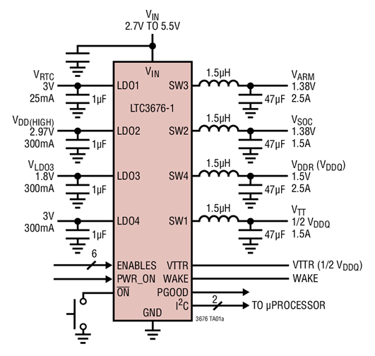
Among its many functions, it offers eight DC rails for the processor core, SDRAM, I/O, system memory, PC cards, always-on real-time clock (RTC), and a variety of other functions:
- Four I2C, adjustable, high-efficiency step-down DC/DC converters (2.5A, 2.5A, 1.5A, and 1.5A)
- Three 300mA LDO regulators (two are adjustable)
- An “always alive“ 25mA LDO regulator
- Independent enables, via pin-strap or I2C sequencing for the eight rails
- Programmable autonomous power-down control
- Power good and reset functions
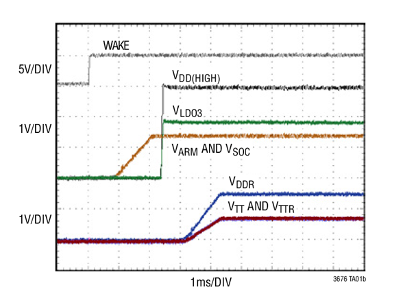
Since it targets a specific class of processor, it also can provide the appropriate start-up sequence and ramp-up slopes for the key DC rails it supplies (Figure 5):
Q: How do I decide among a simpler PMIC, a medium-range one with more features and flexibility, or a high-end one which is application or processor-optimized?
A: As with nearly all engineering decisions, it’s a matter of tradeoffs in performance capabilities, complexity, size, and cost of the solution, as well as other factors. There is no right or best answer, as the answer to deciding on the optimum solution almost always depends on answering this question: “Optimized with respect to which factors, and with what priorities?”
References
- Analog Devices, “Improper Power Sequencing in Op Amps: Analyzing the Risks“
- Audio Express, “Arduino-Based Tube Power Amplifier Controller”
- EEWorld Online, “Load switches, Part 1: Basic role and principle”
- EEWorld Online, “Load switches, Part 2: IC implementations and benefits”
- Texas Instruments, SLVA470, “Sequencing and Tracking With the TPS621-Family and TPS821-Family”
- Analog Devices, LTC3676 Data Sheet
[…] Part 1 of this FAQ has looked at the basics of power-rail management via PMICs or other options. Part 2 will look at some specific PMIC devices and implementations. […]