
The example of an ISL8203M power module shows how designers typically size up the decision between devising a power circuit using discrete components versus spec’ing–in a ready-to-go module.
Jian Yin, Intersil Corp.
Power modules are the way to go when it comes to getting your design to market quickly, but choose wisely. Power-module architecture choices can greatly affect your power supply’s performance for FPGAs, ASICs, microprocessors, DSPs and other-point-of-load conversions in communications, test and measurement, and industrial systems.
Ever-shrinking form factors can adversely affect a system’s electrical and thermal characteristics. So designers must overcome various obstacles in fielding smaller systems. These include the increased likelihood of noise coupling as components are in closer proximity, as well as heat dissipation, given that the power-handling capabilities continue to increase along with smaller footprint areas.
Fortunately, power module designers continue to innovate to meet these demanding requirements through various architecture and topology design approaches. But the techniques used by different power module solutions can greatly affect overall system cost, as well as key performance parameters such as heat dissipation, transient response, ripple voltage, and even ease of use.
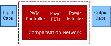
There are many reasons to opt for a power module rather than design a power converter from the component level, not least of which are ease-of-use and time-to-market. By adding only input and output capacitors, power supply designs can be finished easily and quickly. The power module is a complete power converter system in an encapsulated package that includes a PWM controller, synchronous switching MOSFETs, inductors and passive components.
For example, Intersil’s ISL8203M power module has an extremely low profile package at 1.83 mm, similar to a 1206 capacitor’s height. How that module was designed can greatly affect more nuanced parameters, features, and capabilities.
ISL8203M is a complete dc-dc power module optimized to generate low output voltages ranging from 0.8 to 5 V, making it a candidate for any low-power, low-voltage applications. The supply voltage input range is from 2.85 to 6 V. The two channels are 180° out-of-phase for input RMS current and EMI reductions. Each channel is capable of 3-A output current. These channels can be combined to form a single 6-A output in current-sharing mode. While in current-sharing mode, the interleaving of the two channels reduces input and output voltage ripple.
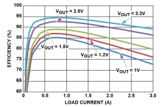
The ISL8203M leverages patented technology and advanced packaging techniques to deliver high power density and excellent thermal performance, allowing it to operate at full load over a wide temperature range. The power module also provides over-temperature, over-current and under-voltage lockout protection. The ISL8203M’s quad-flat, no-lead package is only 1.83-mm thick with a footprint of 6.5 x 9 mm. While the ISL8203M package is compact, it still delivers good efficiency.
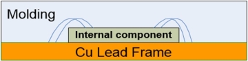
The ISL8203M uses a QFN copper lead-frame package, where the internal component is soldered directly to the copper lead frame. Also, the wire bonds can be applied to the top of the internal component for electrical connections to the lead-frame. Then the molding can be filled in to form a complete encapsulated package.
This structure allows the heat generated by the internal components to be dissipated directly by the copper in the lead frame, which has a thermal conductivity of ~385 W/mK. This is about 1,000 times the thermal conductivity of the printed circuit board (PCB) which has a typical thermal conductivity of ~0.343 W/mK. As a result, the copper-based lead frame can help the heat dissipate much more efficiently than a PCB-based module. Also, because the copper lead frame can be six times thicker than the one-ounce copper on a typical PCB, the module lead frame can help spread the heat over a large area, thus accelerating the effective heat transfer area to the system board.
Overall, the module’s thermal performance can be better than a discrete solution where the component solders directly to the PCB system board.
It’s important to note that the molding material in the structure can have a heat-spreading effect similar to the copper lead frame. Although the molding material has a lower thermal conductivity, the heat can still transfer through the molding horizontally and then dissipate into the copper lead frame. The molding also increases the effective heat transfer area from the internal power component and thus reduces the thermal resistance from the internal part to ambient. Thus power modules have the ability to handle high power in a package smaller than that possible in discrete solutions.
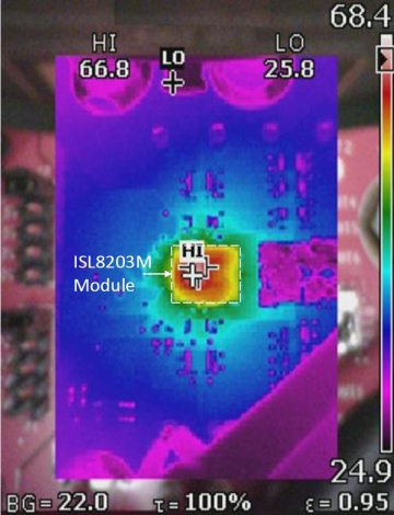
Let’s take a closer look at the thermal performance of an ISL8203M mounted on a standard four-layer evaluation board with two-once copper on the top and bottom layers, and one-ounce copper in the middle layers. Running a worst-case scenario of 5 Vin to 3.3 Vout/6 A with no airflow and an ambient temperature of 25°C, the module’s maximum temperature is only 66.8°C.
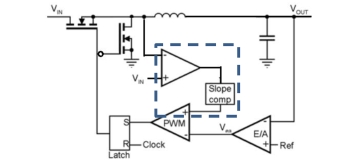
There are generally two types of control schemes used in module applications: current-mode and voltage-mode. To ensure a fast transient response under various load conditions, the ISL8203M uses a current-mode control scheme to regulate the output voltage. The scheme’s current-sensing signal is derived from the voltage across the top FET’s conducting resistance (Rdson) of the synchronized buck converter. This then feeds into the current amplifier, the output of which undergoes slope compensation before being compared to the output error amplifier to generate what now becomes the pulse-width modulation (PWM) signal. Through the driver, the PWM signal can control the synchronized buck converter to get the required voltage regulation. The compensation on the error amplifier is needed to boost the loop gain and phase margin to get better performance and stability.
Finally, the ISL8203M can operate with dual 3-A outputs or a single 6-A output. When it runs at 6 A, the two 3-A outputs can be paralleled. With the phase interleaving between two outputs at 180°, the input and output ripples can be reduced dramatically. More importantly, for a given output ripple, the ISL8203M needs less than half of the output capacitors compared to the single-phase module, thus providing significant cost savings.
All in all, the ISL8203M delivers a total power of 20 W to the load, with the module reaching a maximum temperature of only 66.8°C. Its current-mode control scheme lets it realize good transient performance with excellent peak-to-peak variation and a recovery time that is one-third that of competitive power modules. The ISL8203M’s special parallel mode also enables it to deliver 6 A, with extremely low output ripple, and two outputs interleaved at 180o. This feature also comes with significant component cost savings for a given ripple limit.
These qualities make the ISL8203M a good candidate for any low-power, low-voltage application such as test and measurement, communication infrastructure, and industrial control systems, all needing high density and good performance.
References
ISL8203M data sheet, www.intersil.com/products/ISL8203M
Leave a Reply