Not all power supplies react to over and under-voltages and currents in the same way. It pays to know the tradeoffs of different approaches to protection.
Ron Stull | CUI Inc.
Power supplies can experience operating conditions outside normal specified limits, such as input under- or over-voltage, or variations in load and ambient temperature. These conditions can cause responses such as shutdowns, performance degradation, or component failures. To minimize such difficulties, product designers must know how their supply will perform outside its specified limits.
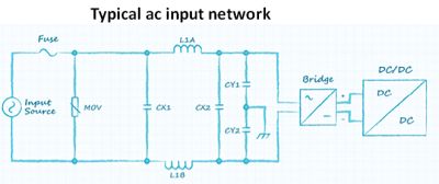
At the power supply input, voltage fluctuations on the ac supply line can over-stress mandatory protection and filtering components such as X-capacitors, Y-capacitors and metal oxide varistors (MOV). These all have known failure modes when exposed to voltages above their rated maximum. X-capacitors, for example, are designed to fail short and will typically open the fuse, shutting down the power supply. Y-capacitors, on the other hand, are designed to fail open. This fault may go unnoticed for some time, although the capacitor will cease to filter common-mode noise effectively.
The effects of over-voltage on the fuse can depend on the fuse voltage rating or its withstand voltage. If the voltage across the fuse exceeds this rating, arcing may prevent the fuse from protecting the circuit as intended. This condition increases the risk of fire and can cause problems at the input or in downstream circuitry.
Over-voltages may also interact with parasitic elements in the power supply circuitry, possibly boosting voltage-related stress on power semiconductors. In a flyback converter, the peak voltage across the power switch is determined by a combination of the input voltage and output voltage as well as the transformer turns ratio and leakage inductance. This peak voltage can be difficult to calculate and typically must be measured directly.
Conversely, under-voltage causes higher currents in components such as the fuse, rectifier and power switches. The result can be extra internal heating that can lead to rapid failure or poor reliability. High current can also introduce a loss of inductance or a saturation of magnetic components such as the PFC (power factor correction) choke. In some topologies, such conditions can cause potentially damaging peak currents in power switches, a rise in their operating frequency, a loss of energy efficiency, or the power supply may shut down.
In other topologies, low input voltage can affect the operating frequency or duty cycle and cause a supply malfunction. In LLC resonant converters, a varying of the operating frequency regulates the output voltage. If the input voltage drops, the frequency slows to boost the input-to-output gain and keep the output voltage stable. However, there is a minimum frequency below which further reduction lowers the gain and so can cause malfunctioning or power-supply failure.
Overvoltage can also affect PFC circuitry. A boost-PFC converter will cease to regulate if the input voltage rises above the output.
Of course, there are several ways to protect the power supply against excessive input-voltage variations. High-wattage power supplies often feature brown-out protection to initiate shutdown if the input voltage falls below a specified threshold. Other protection mechanisms allow the power supply to continue operating, although the performance may suffer. An LLC converter, for example, may clamp the operating frequency at a minimum threshold to prevent malfunctioning. While this helps protect the power supply from failure, it will cause a loss of regulation at the output.
Output over-current
To minimize cost or reduce bulk, designers may be tempted to size the power supply for typical load requirements without considering transient load currents above the chosen rating. Most power supplies contain over-current protection, but there are various types. Some have a well-defined current limit close to the maximum output rating. A too-close current limit can force the supply to shut down frequently.
Other schemes are more flexible and allow short-term output currents to exceed the rated limit. But supplies with this type of protection (or those with no protection) can experience a temperature rise due to over-current that can degrade performance or cause a failure of MOSFETs, diodes, resistors or even copper traces. Note that power dissipation rises linearly with current in diodes, due to their fixed voltage, and exponentially in MOSFETs and resistive components.
Chokes and transformers have a more complex response to over-currents. Besides causing internal heating from coil resistance, over-currents can cause higher core losses and magnetic saturation, worsening power dissipation and heat rise. Saturation may also stop the power supply from operating or make component failures more likely. In a buck converter, where the ripple current is directly related to inductance, loss of inductance due to saturation causes higher currents in the MOSFET and diode.
The effects of parasitic inductances such as transformer leakage should also be considered. These effects can produce voltage spikes when switches change state, becoming larger at higher loads. An excessive spike can destroy a MOSFET or may cause current or voltage sensors to send inaccurate information to the controller, potentially harming performance or causing failure.
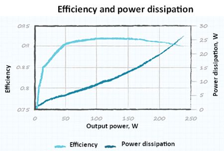
Variations in power supply efficiency, particularly near the maximum rated load, also affect performance and reliability. Efficiency typically peaks below full load. Beyond the peak, efficiency falls, raising power dissipation exponentially as the load rises. The rising dissipation can not only heat up components but also prevent compliance with mandatory efficiency regulations.
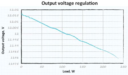
Another consideration is load regulation – the maximum change in output voltage from no-load to full-load. Operation beyond the specified load range can drop the output voltage below the regulated voltage limit. Some smaller power supplies also specify a minimum load current. Operating the unit below this limit can compromise regulation in the same manner as exceeding the maximum load current.
Considering the environment
Power supply selection must also consider environmental conditions. Excessively high or low temperatures can profoundly degrade performance and reliability. Some components, such as electrolytic capacitors, may see a 50% cut in useful life with just a 10°C rise in ambient temperature. Alternatively, low temperatures can cause problems such as embrittlement of solder joints, connections or component leads, resulting in early failure.
Both upper and lower operating temperature limits are defined to ensure components will operate as their manufacturers specify. Their performance cannot be guaranteed outside of this range. Ignoring temperature limits may degrade the power supply efficiency, output ripple, regulation or noise-emission parameters.
Key components of the power supply may have either a positive or negative temperature coefficient (PTC or NTC). MOSFETs are PTC devices whose on-resistance rises with rising temperature. Bridge rectifier diodes, on the other hand, are NTC devices; as the forward voltage drops with increasing temperature, so, too, does internal power dissipation and heat generation. Depending on the individual power supply, either the NTC or PTC devices will dominate as the temperature changes, causing the overall supply efficiency to rise or fall.
Resistors used to sense operating conditions and control the power supply typically carry little current, so they are generally not vulnerable to excessive heating or power dissipation. But temperature change affects their resistance value. The resistance change may lead to unwanted changes in power-supply parameters such as the regulated output voltage. Other effects can include early or late triggering of protection mechanisms that depend on sensed current.
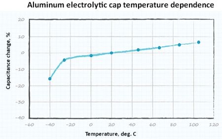
At low temperatures the capacitance of electrolytic capacitors drops, resulting in more ripple current or a failure of the power supply to start up. In addition, the resistance of NTC devices, such as inrush-current limiting thermistors, will rise as the ambient temperature falls, which can reduce efficiency or prevent start up.
Some power supplies contain over-temperature protection and will shut down until the temperature drops within the specified limit. Others may only include protection for specific components or sub-circuits, a practice which can cause problems if some parts of the power supply shut down while others continue operating.
PTC devices such as MOSFETs are usually designed-in with some safety margin to protect against over-temperature. However, the margin depends on operating conditions such as input voltage and may be narrower in some parts of the operating range than others.
Finally, designers should investigate the effects of over- or under-voltage on electromagnetic emissions (EMI). Over- or under-voltage at the input, or output over-current, can alter the properties of EMI-filtering components or cause over-stress that can impair their performance. Although difficult to estimate, the effect can be significant and may result in a failure to comply with EMC regulations.
In all, designers must understand how a power supply may respond to all changes in input, output or environmental conditions, whether they are within specified limits or not. This kind of information helps designers assess system performance, reliability, longevity and compliance with technical regulations.
References
ac-dc power supplies, https://www.cui.com/catalog/power/ac-dc-power-supplies
dc-dc converters, https://www.cui.com/catalog/power/dc-dc-converters



Leave a Reply