
“Noise”—perhaps nothing worries design engineers as much as the implications of this single five-letter word. There are good reasons for this worry. Noise is often unpredictable; may come from internal and somewhat controllable sources, or external impossible-to-control sources; it can affect performance accuracy and consistency; it can cause products to not meet their target design objectives; and it random-like failures in prototype stages as well as in the field.
Given the wide-ranging sources and manifestations of noise, there are thousands of articles, application notes, and design tips which explain noise and how to approach it. (Warning: often this multitude of advice is contrary, but that is usually due to differences in the applications reality and author experience.) In this FAQ, we’ll focus on noise beginning with the system’s AC/DC supply, although many of the points apply to DC/DC supplies (also called converters or regulators) as well.
Q: Why look at power-supply noise? Isn’t it more important to look at noise at the circuitry, especially low-level analog ones?
A: A power supply’s output rails are the foundation on which the circuit and system are built. If there is noise on these rails, the system’s ability to function as designed is compromised. Many times, problems due to power-supply noise are intermittent and inconsistent, making them very hard to confirm. Plus, every system has a power supply (except, perhaps, an extremely simple one such as a battery driving an LED via a current-limiting resistor), and therefore the supply is a potential noise source in nearly every design
Q: The term “EMI” (electromagnetic interference) is used quite a bit. What are the mechanisms for generating this EMI?
A: There are four dominant mechanisms:
Conductive coupling is a physical-coupling path that is formed by a direct contact. In addition to a cable or wire, such coupling can also occur with any trace on a printed circuit board (PCB) or even a metal enclosure.
Radiative coupling occurs through the air or vacuum. As every trace on a PCB is a potential antenna, it is also a potential coupling path.
Capacitive coupling is related to an electric field, and occurs when a varying electrical field exists between two adjacent conductors. For instance, when there are two plates with a potential difference separated by any space, it forms a capacitor.
Lastly, there’s inductive coupling, which is related to the magnetic field and occurs when there is a varying magnetic field between two parallel conductors; this results in parasitic induced voltages.
In general, in high-voltage applications, capacitive coupling dominates, while inductive coupling dominates in high-current situations.
Q: Should I be worried about noise, if my circuit seems to be working fine?
A: Probably. Even if the supply noise is not affecting your system, there are various regulations and mandates about how much noise your product, including the supply, is allowed to emit. Since power supplies usually have relatively long leads or PC board traces, the supply’s noise may be radiating out as these wires act as antennas. These regulatory standards are part of the category of electromagnetic compatibility (EMC) regulations.
Q: What’s the difference between EMI and EMC?
A: Every electronic device emits EMI, or electromagnetic interference, while the effect that the device has on other electronic devices is where EMC comes in.
EMC, or electromagnetic compatibility, covers with how well the product interacts with other products within its environment.
Q: What standards does my system have to meet?
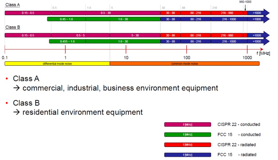
A: This is a simple question with a complicated answer. It is a function of the operating frequency, power levels, and application. The two most common are regulations cited are CISPR 22 and FCC 15;
–CISPR 22 tests for conducted noise from 150 kHz to 30 MHz, and for radiated noise from 30 MHz to 6GHz.
–FCC 15 tests for conducted noise from 450 kHz to 30 MHz, and radiated noise from 30 MHz to 40GHz or the fifth harmonic of the highest frequency in the circuit.
Q: That’s all there is to it?
A: Not at all. There are worldwide standards defined by the IEC, and European standard designated as EN. Each of the standards actually has many categories, sub-categories, and sub-sub-categories, including differentiating equipment designated as Class A and Class B. Class A is for commercial, industrial, and business environment equipment, while Class B is for residential environment equipment. The tests for Class A are more stringent because of the environments in which they operate. Different conductive and radiated test performed at the same frequency, for both classes, Figure 1.
In general, unless a product team has a skilled in-house EMI/EMC group, it’s may make sense to not try to figure out the relevant standards and setups., but instead use a qualified consultant or certified EMC Lab. These labs are also responsible for conducting the required tests and issues the formal certificates of compliance.
Q: In general terms, what are the sources of noise in power supplies?
A: For a linear supply, the self-generated noise is very low, as an inherent consequence of its architecture. Noise in a linear supply output is usually the result of radiated pickup by these leads and possible re-radiation.
In contrast, a switching supply (formally called switched-mode power supply, or SMPS) does generate noise, again as a consequence of it operating principles; some are available which are especially designed to minimize noise.
Q: What’s the first (and easiest) thing to do when you have a noise issue with power-supply wiring?
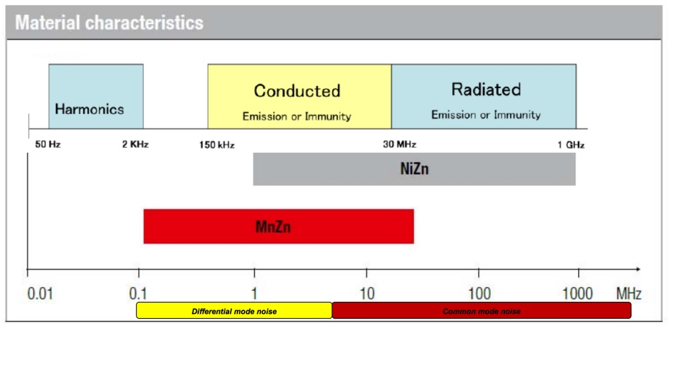
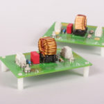
A: Here, the answer is simple: ferrite beads placed around the supply output leads. These beads (which range in size from about one-half to several centimeters in diameter, used a mix of magnetic ferrite materials (Figure 2) to attenuate RF signals as they pass along the wire, yet have no effect on the DC current coming from the supply. The ferrites are typically made with two different types of materials: manganese zinc and nickel zinc. Nickel zinc is used in situations with either conducted or radiated noise, while manganese zinc is used mostly for conductive noise.
These ferrites are a low-cost, no-risk solution with no after=effects, and often used as a standard part of the “we’ll use them just in case” approach in the initial designs. They are also often added afterward as soon as a problem arises since they are easy enough to give a try.
Q: There’s a reference to common mode noise and differential noise –what’s that about?
A: These two noise sources and their solution will be discussed in Part 2.
References
- Radio-Electronics.com, “Resolving EMI common mode & normal mode noise”
- Pulse Electronics, “Understanding Common Mode Noise”
- Murata, “Differential and Common Mode Noise”
- Murata, “Conditions for Electromagnetic Interference and Future Trends”
- Würth Elektronik GmbH, “EMC Basics: Common Mode vs. Differential Noise” (and previous blogs in the series)

Leave a Reply