• Skip to primary navigation
  • Skip to main content
  • Skip to primary sidebar
  • Skip to footer
  • Subscribe
  • Advertise

Power Electronic Tips

Power Electronic News, Editorial, Video and Resources

  • Products
    • Power Supplies
    • AC-DC
    • DC-DC
    • Battery Management
    • Capacitors
    • Magnetics
    • MOSFETS
    • Power Management
    • RF Power
    • Resistors
    • Transformers
    • Transistors
  • Applications
    • 5G
    • AI
    • Automotive
    • EV Engineering
    • LED Lighting
    • Industrial
    • IoT
    • Wireless
  • Learn
    • eBooks / Tech Tips
    • EE Training Days
    • FAQ
    • Learning Center
    • Tech Toolboxes
    • Webinars & Digital Events
  • Resources
    • Design Guide Library
    • Digital Issues
    • Engineering Diversity & Inclusion
    • LEAP Awards
    • Podcasts
    • White Papers
    • Design Fast
  • Video
    • EE Videos & Interviews
    • Teardown Videos
  • EE Forums
    • EDABoard.com
    • Electro-Tech-Online.com
  • Engineeering Training Days
  • Newsetter Subscription

Power-supply noise, Part 2

January 26, 2018 By Bill Schweber

Part 1 looked at the basics of noise, especially concerning power supplies. There are two noise sources which are not as obvious to many engineers as noise that results from the switching action of the power supply: differential mode noise and common-mode noise. These two noise modes have different causes and thus different solutions

Q: What is differential mode noise?

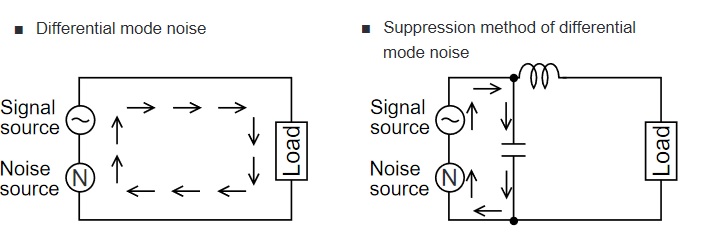
Differential mode noise (often referred to simply as differential noise) is noise which is conducted on the line and neutral wire in opposite directions, Figure 1, left side.

power supply noise
Fig 1: (left) Differential mode noise is conducted on the line and neutral in opposite directions; (right) it can be filtered by a single-winding inductor in the line path and a capacitor from line to neutral. (Source: Murata Manufacturing Co., Ltd)

Q: What is the best solution to deal with differential mode noise?

A: A choke (inductor) placed as shown will usually handle the problem. The basic differential mode noise filter uses a single-winding choke which is inserted into the line path, along with a capacitor from line to neutral, thus blocking noise from propagating through the system, Figure 1, right side.

Since the differential mode noise inductor is in the line path, it handles both the noise and the DC offset due to the current being supplied to load. Therefore, it must be designed to provide the needed inductance but do so with low DC resistance (DCR) to handle both the RMS current and the peak line current without saturating. If the current level is low, a chip-style ferrite-bead component can be used.


Q What is done to reduce common mode noise?

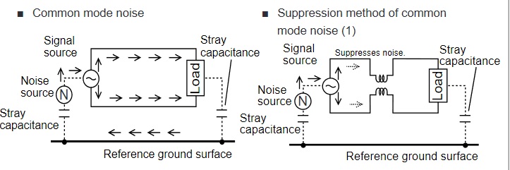
A: Again, a specialized inductor is the answer. The basic common-mode noise filter uses a dual-winding inductor in both line and neutral paths, plus a capacitor from line to ground, Figure 2, right side. Since the line and neutral currents pass through the common-mode windings in opposite directions, there is no net DC flux and therefore no possibility of saturating the choke’s magnetic core. The common mode choke only needs to have the required inductance along with sufficiently low DC resistance (DCR) for the RMS current.

power-supply noise
Fig 2: (left) Common mode noise is conducted on both the line and neutral (ground) but in the same direction; (right) a dual-winding inductor in both line and neutral paths, plus a capacitor from line to ground, can effectively filter it. (Source: Murata Manufacturing Co., Ltd)


Q: Is there a way to tell which type of noise problem is in the design?

A: Yes, to some extent. First, apply a clamp-on ferrite onto a cable, remembering both lines (DC power and ground) will be in that cable. If the noise is reduced, or the immunity is increased, that indicates common mode problem; if there’s no effect, it’s likely a differential mode problem. If there is a common mode problem, try a common mode choke. If it’s a differential mode problem, use a chip bead ferrite or a differential mode choke.

In general, for frequencies above 10 MHz, it is most likely a common mode noise issue, but not guaranteed. It’s possible to have differential noise above 10 MHz, but that doesn’t happen very often.

References

  1. Radio-Electronics.com, “Resolving EMI common mode & normal mode noise”
  2. Pulse Electronics, “Understanding Common Mode Noise”
  3. Murata, “Differential and Common Mode Noise”
  4. Murata, “Conditions for Electromagnetic Interference and Future Trends”
  5. Würth Elektronik GmbH, “EMC Basics: Common Mode vs. Differential Noise” (and previous blogs in the series)


You may also like:

  • power-supply noise
    Power-supply noise, Part 1

  • Power supply noise rejection – Technical Brief

  • Three common mistakes when designing power supplies

Filed Under: FAQ, Featured, Industry Experts Tagged With: basics, FAQ, murata, würthelektronik

Reader Interactions

Trackbacks

  1. Power-supply noise, Part 1 - Power Electronic Tips says:
    January 26, 2018 at 1:11 pm

    […] A: These two noise sources and their solution will be discussed in Part 2. […]

  2. [Solved] Common Mode Noise on Differential Lines Driven Against Chassis GND – Ten-tools.com says:
    October 4, 2022 at 5:20 am

    […] REFERENCE IMAGE 1: Choke on single-ended signal and system GND. Image Source […]

Primary Sidebar

Featured Contributions

Robust design for Variable Frequency Drives and starters

Meeting demand for hidden wearables via Schottky rectifiers

The case for vehicle 48 V power systems

GaN reliability milestones break through the silicon ceiling

Developing power architecture to support autonomous transportation

More Featured Contributions

EE LEARNING CENTER

EE Learning Center

EE TECH TOOLBOX

“ee
Tech Toolbox: Internet of Things
Explore practical strategies for minimizing attack surfaces, managing memory efficiently, and securing firmware. Download now to ensure your IoT implementations remain secure, efficient, and future-ready.

EE ENGINEERING TRAINING DAYS

engineering
“power
EXPAND YOUR KNOWLEDGE AND STAY CONNECTED
Get the latest info on technologies, tools and strategies for EE professionals.
“bills

RSS Current EDABoard.com discussions

  • ISL8117 buck converter blowing up
  • audio transformers impedance
  • GS transmission line simulation wave port setting
  • CRT TV (Sony) horizontal lines appears for a few minute and go way
  • avoiding mixer compression when acting as a phase detector

RSS Current Electro-Tech-Online.com Discussions

  • RS485 bus: common ground wire needed or not?
  • Good Eats
  • What part is this marked .AC ?
  • Photo interrupter Connections
  • How to balance Milwaukee M18 tool batteries

DesignFast

Component Selection Made Simple.

Try it Today
design fast globle

Footer

EE World Online Network

  • 5G Technology World
  • EE World Online
  • Engineers Garage
  • Analog IC Tips
  • Battery Power Tips
  • Connector Tips
  • DesignFast
  • EDA Board Forums
  • Electro Tech Online Forums
  • EV Engineering
  • Microcontroller Tips
  • Sensor Tips
  • Test and Measurement Tips

Power Electronic Tips

  • Subscribe to our newsletter
  • Advertise with us
  • Contact us
  • About us

Copyright © 2025 · WTWH Media LLC and its licensors. All rights reserved.
The material on this site may not be reproduced, distributed, transmitted, cached or otherwise used, except with the prior written permission of WTWH Media.

Privacy Policy