
Engineers who deal with power supplies (as most eventually do) often see the circuit-protection terms “crowbar” and “clamp.” No, there are no references to items purchased at the local hardware store, but they are essential “hardware” elements, meaning autonomous circuit components and functions with no related software. They are used to provide protection to a load or system from supply failures, whether short-term transients or “hard” failure. This FAQ will examine the role and implementation of these to widely used supply-related functions, often categorized as overvoltage-protection (OVP) circuits.
Q: What are the challenges of an OVP circuit function?
A: It must do five things:
- Obviously, prevent any excessive voltage from appearing at the protected components;
- Not interfere with normal operation, but be “invisible” and not “load” the power supply;
- Distinguish between normal voltage fluctuations and excessive overvoltage;
- Be fast, and respond before the load is damaged when a genuine overvoltage situation does occur;
- Not have false positives (false trips) which are a nuisance, and also not fail to respond to real overvoltage conditions.
Q: What is the role of these crowbars and clamps?
A: They are circuit functions usually added to a power supply output (or even a subcircuit itself) to protect the load and system from gross malfunctions and failures of the supply as well as transient events such as brief voltage spikes.
Q: What s the difference between the crowbar and the clamp?
A: A crowbar puts a short circuit across the output of the supply, thus diverting the supply’s output current to ground, and so forcing the output voltage to zero (or close to zero) volts (Figure 1). For most crowbar designs, the crowbar action will automatically return to normal operation when the overvoltage condition is removed; in some implementations, power must be removed entirely to stop its conduction.
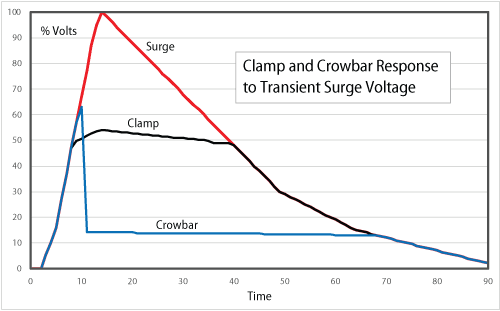
In contrast, a clamp prevents the voltage from exceeding a preset level. Clamps can also be called transient voltage suppressers (TVS), since they may be protecting against a start-up transient or inductive transient rather than an actual failure. Another difference is that a TVS handles short spikes, while a full clamp can function for the duration of the in many cases. For most clamps, the clamp function releases when the overvoltage condition clears.
Compared to a clamp, the crowbar’s low holding voltage lets it carry a higher fault current without dissipating much power, so it can handle higher currents and do so for longer periods. It is also easier to configure the circuit so that the crowbar also causes a fuse to blow (and thus stop current flow completely) if that is desired.
Q: How does a crowbar work?
A: The crowbar normally is a high-impedance circuit across the supply output (or input of the load to be protected). It becomes a low-impedance circuit when the overvoltage situation occurs and triggers it, and stays in low-impedance mode until the current decreases below the “holding current,” then it returns to the high-impedance, normal-operation state. The crowbar must be able to handle the current flowing through it for the amount of time the supply is in overvoltage state.
Q: How do you build a crowbar?
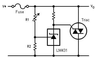
A: The circuit is relatively simple: In the example below (Figure 2), an LM431 adjustable Zener regulator controls the gate voltage of the TRIAC, with R1 and R2 as a voltage divided providing the reference voltage for the LM431 (in some designs, a “plain” Zener diode is used rather than a regulator; also, fixed resistors can also be used for a non-adjustable circuit). Normally, the voltage across R2 is slightly lower than reference voltage of the regulator, so it remains off, and the LM431 looks like a high impedance with little current flow. If the supply voltage increases beyond the threshold, the voltage across R2 will exceed the reference voltage, the LM431 will begin to draw current, and TRIAC will be triggered and latched on. (Of course, there are many other variations of this circuit.)
Q: Are there discrete crowbar devices?
A: Yes. The most common crowbars are based on Thyristor Surge Protectors (TSPs), which are silicon-based PNPN devices with a breakdown voltage can be set precisely by their manufacturer. They are offered in many package types and can dissipate various levels of surges.
The other commonly used crowbar device is the Gas Discharge Tube, (GDT) which is a miniature spark gap usually housed in a ceramic enclosure. When triggered by a high voltage, the spark gap conducts, and all current flow is diverted. Spark gaps can be manufactured such that they protect from modest voltages (around 100 V) to thousands of volts such as from lightning, When the overvoltage situation clears, the TSP or GDT goes back to normal, high-impedance mode.
Part 2 of this FAQ will look at a complementary OVP device, the clamp, in more detail.
References (all EEWorld Online)
Why use an e-fuse? Part 1
e-Fuses, Part 2: Building or buying an e-Fuse
Fuses for power protection, Part 1
Fuses for power protection, Part 2
Load switches, Part 1: Basic role and principle
Load switches, Part 2: IC implementations and benefits
Programmable electronic fuse sustains 4 A over 8 to 48-V range
Fuses that blow safely
Six considerations for better circuit protection
Basics of power-supply self-protection
Varistors include fuse protection
Radial leaded MOVs for general purpose overvoltage protection
Other References
Microsemi Corp, MicroNote 106, “Crowbars and Clamps: What Are Their Major Differences?”
Sunpower Electronics Ltd, “What is Over Voltage Protection?”
Bourns, Inc., “Transient Overvoltage Protection”


Leave a Reply