
Anant Kamath, Systems Engineer, Texas Instruments, Inc.
Recent advances in isolation technology are enabling new solutions, reducing system cost, and allowing customers to push the performance envelope of their equipment. This article discusses key end applications that are driving cutting-edge innovations in isolation technology and benefitting from these innovations.
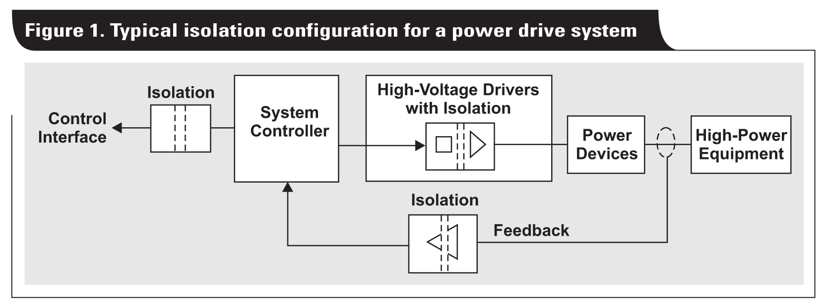
Isolation is a means of preventing DC and uncontrolled AC currents between two parts of a system, while allowing signal and power transfer between those two parts. Electronic devices and integrated circuits (ICs) used for isolation are called isolators. Isolation is required in modern electrical systems for a variety of reasons. Some examples include protecting human operators and preventing damage to expensive processors in high-voltage systems, breaking the ground loop in communication networks, and communicating to high-side devices in motor-drive or power-converter systems (Figure 1). Examples of applications that need isolation include industrial automation systems, motor drives, medical equipment, solar inverters, power supplies, and electric vehicles (EVs).
Reinforced isolation
Reinforced isolators are devices that can provide insulation equivalent to two basic isolators in series. By themselves, reinforced isolators are considered sufficient to ensure electrical safety against high voltage. However, reinforced isolators must satisfy increasingly tighter performance requirements. Motor-drive applications have the most stringent specifications for reinforced isolation because these systems use very high incoming supply voltages and they involve interfaces accessible to human operators. The requirements for isolation in motor control are defined in safety standards. For example, the IEC 61800-5-1 electrical, thermal and energy safety standard for adjustable speed drives. According to this standard, the requirements on reinforced isolation scale up with an increase in the system voltage which is defined as the root-mean-square (rms) voltage between incoming supply lines and earth.
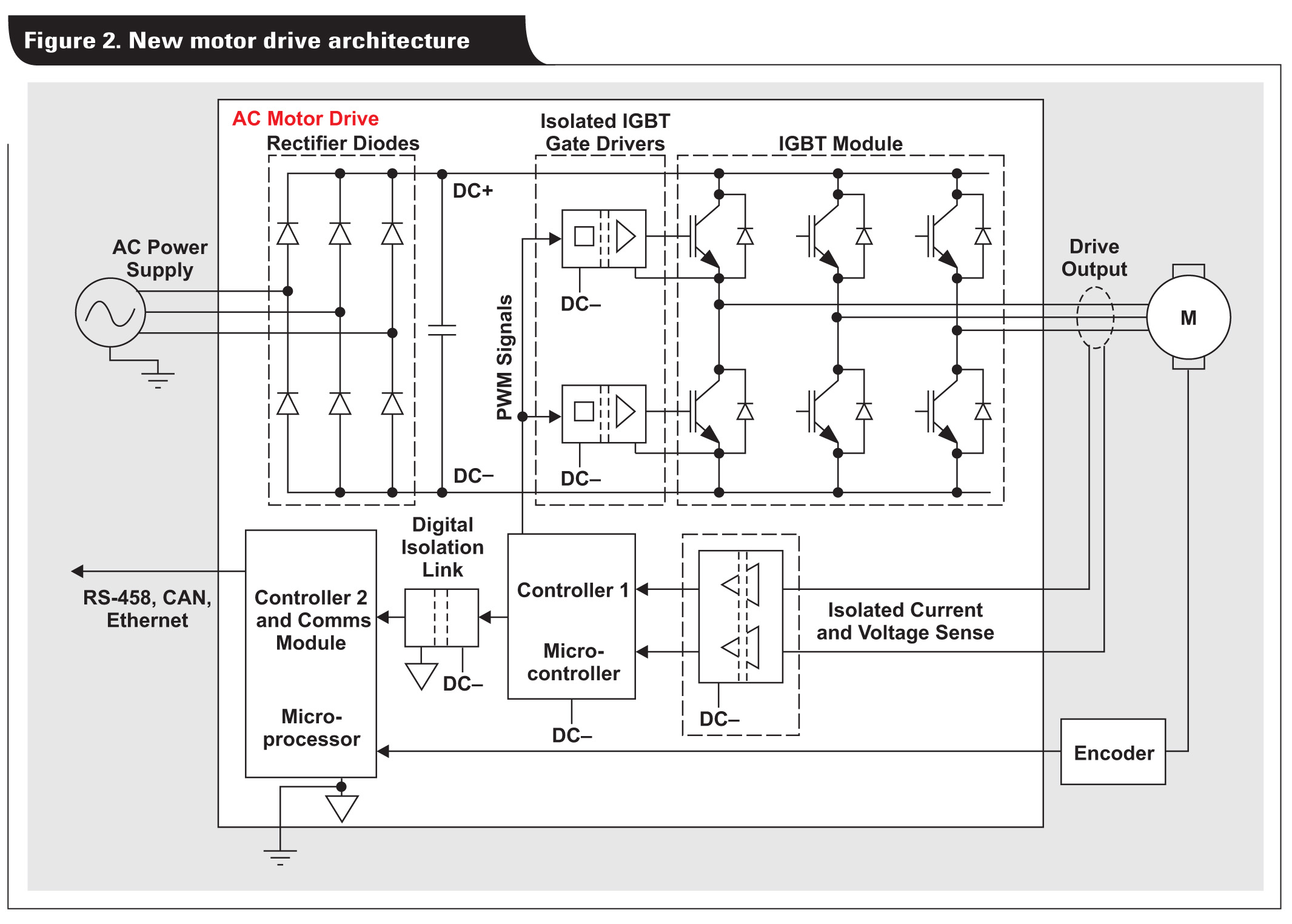
To guarantee reinforced insulation for drives with system voltage greater than 600 VAC, an isolator must withstand a 5-second temporary overvoltage of at least 4400 VRMS. This isolator also must have a surge voltage capability of at least 12 kVPK, creepage and clearance of at least 14 mm, and a working voltage in the range of 600 VRMS to 1000 VRMS, which depends on the supply line voltages and drive architecture. To make matters more challenging, new motor-drive architectures are adding local field-programmable gate arrays (FPGAs) and controllers to the power board referenced to the DC bus (Figure 2, controller 2). This reduces the local isolation requirement on the power board. However, it increases the data rate and bandwidth requirement on one, multichannel integrated, high-speed reinforced link (Figure 2, digital isolation link). Until recently, isolators meeting these isolation requirements, as well as the timing and data rate requirements, were not available in the market. The only alternative was fiber-optic isolation.
Capacitive reinforced isolation solutions are now available that meet the above requirements for high isolation, wide packages, and high data rates. These solutions are a good fit for motor-drive applications with system voltages beyond 600 VAC. Some optocouplers do meet the high-isolation requirements, but do not meet the data rate or multichannel integration requirements. Additionally, leading magnetic-isolation solutions do not meet the requirement on working voltage/long-term reliability.
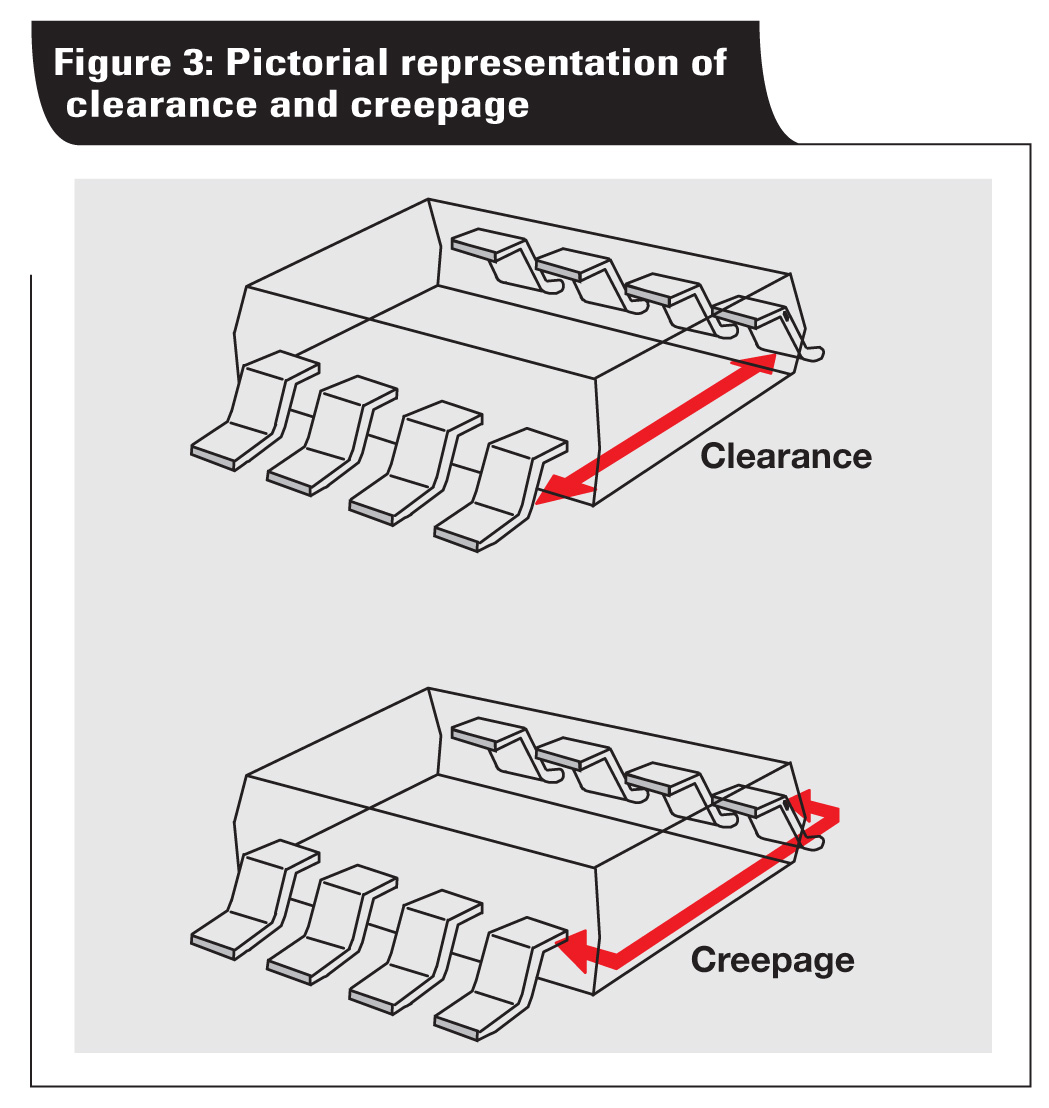
Examples of creepage and clearance are illustrated in Figure 3.
High working voltage
Solar and wind energy applications generally use additional isolation barriers (for example, in the path of the network-communication channel) to achieve reinforced isolation. Hence, the requirements related to reinforced isolation are not as high as in motor-drive applications. However, the requirement for high working voltage can exceed values seen in motor drives. Power plant centralized solar inverters and wind-energy inverters are trending to operate with higher DC bus voltages, extending to 1500 V and beyond. Higher DC-bus voltages enable higher power ratings without increasing the current levels, which keeps copper costs the same. This helps reduce the per-unit cost of energy generated. Another bonus of higher voltage is increased efficiency because the total power output can increase with higher voltage, but when current does not change, the conduction losses also remain the same.
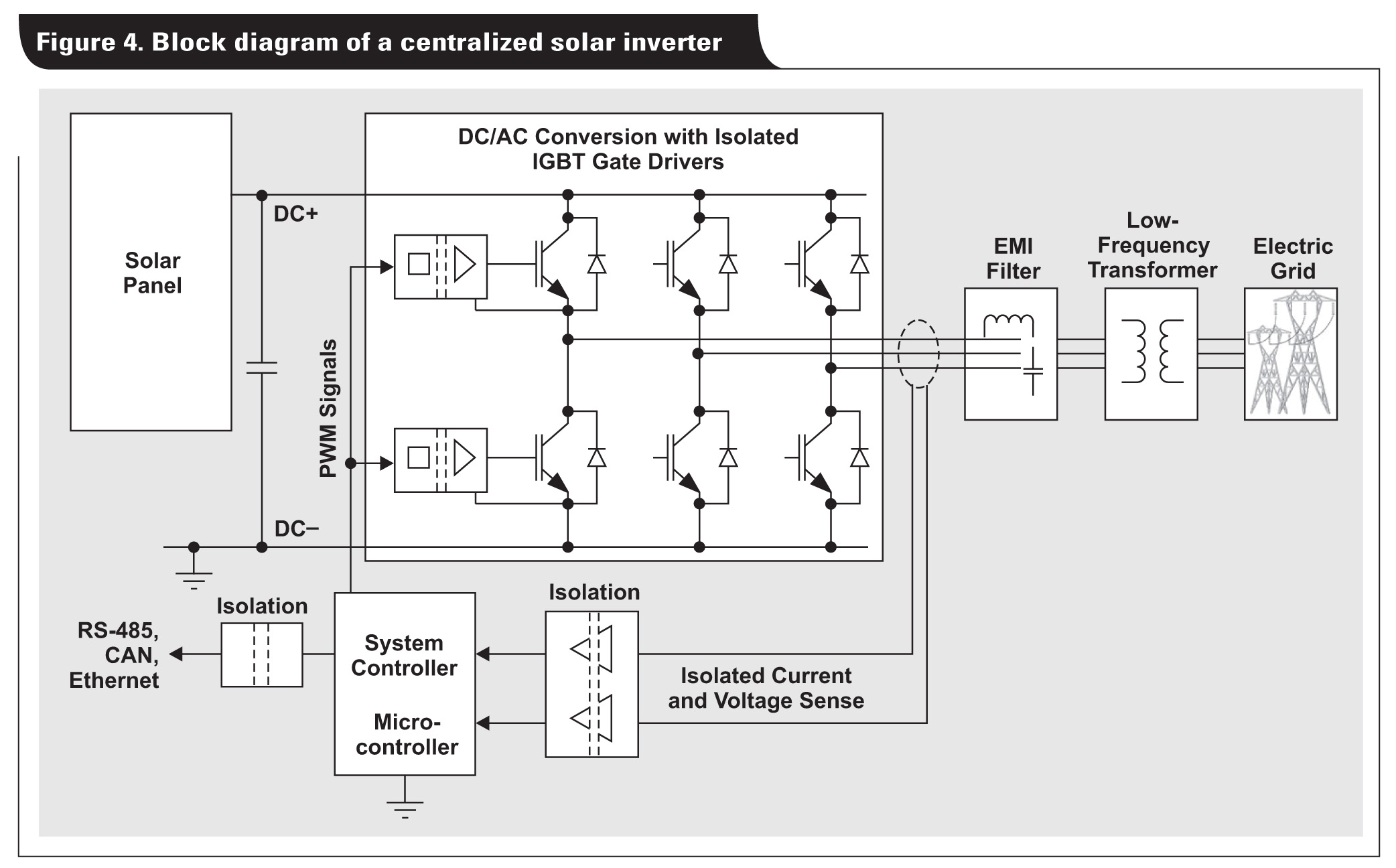
Higher DC bus voltages directly translate to higher working voltages for the isolators used in switching power transistors in the inverter. In Figure 4, the isolated gate drivers (or any digital isolators paired with discrete gate drivers) continuously see a trapezoidal voltage. These voltages appear between one side that is connected to the inverter output, and the other side is connected to earth reference. The peak-to-peak value of this voltage waveform is the DC link voltage. For any isolator, its lifetime degrades exponentially with increased voltage stress across the barrier. Solar and wind inverter systems target lifetimes in excess of 25 years. It is critical to choose an isolator that meets the working-voltage requirement with a liberal margin so that the lifetime of the complete system is not limited by the isolators.
New capacitive isolators achieve a working voltage of 1500 VRMS (2121 VPK). This voltage is a 50% increase compared to commonly available devices, which enables higher-voltage and more efficient inverter systems at a lower cost. Optocouplers have fair isolation and working-voltage performance; however, the LEDs they use limit their lifetimes from an electrical-performance point of view. As mentioned earlier, leading polyimide-based, magnetic-isolation technologies have low working voltage ratings and low long-term insulation reliability, which limits their use in high-voltage, solar-inverter applications.
High common-mode transient immunity
Common-mode transient immunity (CMTI) is the ability of an isolator to tolerate high-slew-rate voltage transients between its two grounds without corrupting signals passing through it. In electric-vehicle motor drives, as well as solar- and wind-energy inverter applications, the isolated gate drivers or isolators passing gate controls to power transistors see large ground transients because one ground is connected to rapidly switching inverter outputs. Figure 5 shows the ground potential difference experienced by these gate drivers. In these systems, CMTI is a critical parameter because any bit errors caused by the transients can result in dangerous short-circuit events.
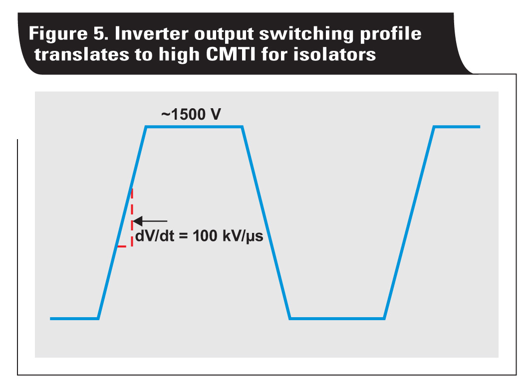
Recent application requirements are pushing the need for isolators with higher and higher CMTI. As stated, one requirement is increasing DC bus voltages. A second is reducing transition times with faster switching in the power transistors, which improves inverter efficiency. A third is increasing switching frequency, which results in lower-cost and less-bulky magnetics such as inductors, transformers and motors. Availability of reliable silicon-carbide or SiC-based power transistors, which can switch faster and tolerate higher voltages versus traditional IGBTs, is building on the trend for inverters that switch faster and more efficiently.
Capacitive isolators released in 2014 broke the barrier for 100-kV/?s CMTI. Capacitive isolators and gate drivers continue to lead the industry with the highest minimum guaranteed CMTI, thus enabling faster, more efficient, and lower-cost inverter designs.
High-altitude operation
Advanced packaging technology is required for isolators used in equipment operating at higher altitudes and in a polluted or high-moisture environments. Improved and wider packages prevent degradation along the package surface and arcing through the air between pins, which ensures isolation quality. Isolators used in solar, wind-energy and e-metering applications fall into this category.
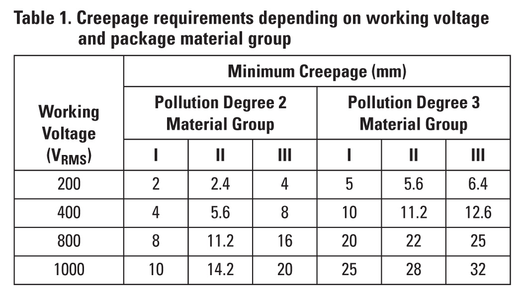
Isolator voltages that continuously operate in heavy pollution can cause package surfaces to degrade and create a conductive path across the isolator. This phenomenon is called tracking. Choosing a higher-quality packaging mold compound that belongs to a lower material group with higher comparative tracking index (CTI) can minimize this effect for a given package creepage and working voltage. Another approach is to choose a wider package with increased creepage to reduce the risk of tracking.
Table 1 shows the requirements on creepage distances depending on working voltage, the pollution degree, and the material group of the isolator’s package mold compound for reinforced isolation, according to IEC 60664-1. The requirements on creepage increase with working voltage and pollution degree, however, selecting a lower material group with a higher CTI can reduce the creepage requirement.
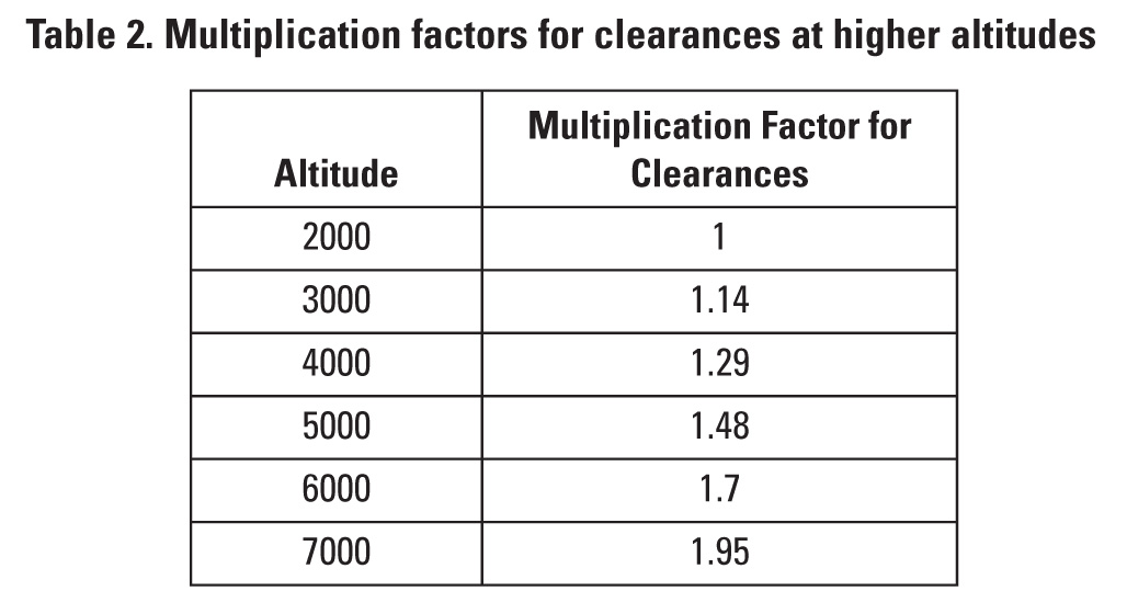
At higher altitudes of 2000 to 5000 meters above sea level, the air pressure is lower. Therefore, peak overvoltages, such as surge or temporary overvoltage, can more readily cause arching between the isolator pins. Equipment operating at high altitudes requires greater spacing between pins (more clearance). Table 2 shows the multiplication factors by which clearance must be increased at higher altitudes to prevent arcing per IEC 60664-1.
Traditionally, conformal coating or potting techniques involving deposition of insulating polymer or other material over the printed circuit board (PCB) have been used to reduce the pollution degree around the isolator. This reduces the requirement on creepage and clearance. However, these methods add cost, are less reliable, and need additional inspection steps in PCB manufacturing. Wide-body isolators manufactured with high-quality molding compounds eliminate the need for conformal coating or potting, simplify PCB design, and increase manufacturing reliability.
New isolators use the best quality mold compound (CTI material group I) and are available in wide packages (14.5 mm creepage/clearance). These isolators can enable high-altitude designs and tolerate higher pollution without requiring additional steps in PCB manufacturing.
Capacitive digital isolators
Recent advances in capacitive digital isolators place them at the forefront of technology. These new isolators offer higher isolation performance, long-term reliability, increased channel integration, higher data rates and precision timing performance, better quality package mold compound, wider packages (14.5-mm creepage/clearance), and CMTI exceeding 100 kV/?s. Combining these features enables new applications, reduces system cost, and allows end-equipment manufacturers to push the performance envelope of their solutions.
Texas Instruments offers the ISO78xx family of reinforced digital isolators and the ISO585x and ISO545x families of reinforced isolated IGBT gate drivers. These isolators offer features and capabilities that can solve difficult isolation problems. These isolators have a working voltage of up to 1500 VRMS, are rated for 40 years, have surge voltage capability of 12.8 kV, and withstand a temporary overvoltage of 5700 VRMS. They offer high data rates of up to 100 Mbps with low skews and part-to-part variations and CMTI exceeding 100 kV/us. They also use material group I mold compound and are available in industry-leading wide packages.
References
1. IEC 61800-5-1 Ed. 2.0, Adjustable speed electrical power drive systems, safety requirements, electrical, thermal and energy. July 2007
2. Anant S Kamath and Kannan Soundarapandian, “High-voltage reinforced isolation: Definitions and test methodologies,” Texas Instruments White Paper, November 2014 (SLYY063)
3. Anant S Kamath, “Isolation in AC Motor Drives: Understanding the IEC 61800-5-1 Safety Standard,” Texas Instruments White Paper, November 2015 (SLYY080)
4. IEC 60664-1 Ed. 2.0, Insulation coordination for equipment within low-voltage systems, principles, requirements and tests, April 2007
Texas Instruments, Inc.
www.ti.com
Leave a Reply