As discussed in part 1 of this series, physical RF transformers are non-ideal devices and include parasitic resistances, inductances, and capacitances, which are non-linear and complex effects that compromise performance. Several fabrication methods have been developed to mitigate the impact of the various parasitics and help to optimize RF transformer characteristics for the needs of specific applications.
Core-and-wire transformers
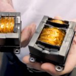
Core-and-wire designs are the most-common form of RF transformers. Selection of the optimal core material is an important design consideration for core-and-wire transformers (see Part 1 of this series for information on core materials). In these designs, magnetic flux forms in the core as a result of current flow in the primary winding. The resulting current in the secondary winding is related to the turns ratio between the two windings. In a transformer with an iron or powdered core, the exciting current required for inducing the secondary voltage is a small percentage of the load component of current. In an air-core transformer, the primary current induces a secondary voltage proportional to the mutual inductance since all of the current is exciting current.
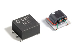
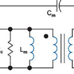
Core-and-wire transformers include parasitic resistances, inductances, and capacitances, which are non-linear and complex effects. These devices operate with a limited bandwidth, have insertion loss, a maximum power rating, and exhibit other frequency-, temperature- and power-dependent performance. Specification of these and other non-ideal characteristics are discussed in more detail in Part 3 of this series on RF Transformer Specification.
Transmission line RF transformers
A basic transmission line transformer consists of a two-conductor transmission line. These designs have a wider operating bandwidth compared to core-and-wire transformers since the transmission line contains some of the interwinding capacitance and leakage inductance. However, only a limited number of ratios (such as 1:9, 1:4 or 1:2) can be achieved with this technique.
Insulated wires wrapped around a ferrite core can also produce a transmission line RF transformer. This topology is often considered to be a subset of core-and-wire RF transformers.
Transmission line transformer topologies are versatile and include precision transmission lines placed between two mismatched loads or a complex arrangement of several transmission lines. A length of transmission line can also be used to implement an impedance transformation between two mismatched loads.
LTCC transformers
Low temperature co-fired ceramic (LTCC) transformers are multilayer devices that use coupled lines as transmission lines to achieve impedance transformation and signal conversion from single-ended to balanced. Unlike wire-and-core components, LTCC transformers rely on capacitive coupling, enabling LTCC transformers to operate at higher frequencies compared to ferromagnetic transformers.
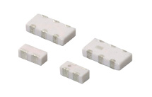
This may lead to performance degradation at low frequencies compared with larger coil-and-wire and transmission line RF transformers. For higher-reliability and higher-performance systems that benefit from smaller, more rugged transformers, LTCC technology is often the preferred choice.
Baluns
Controlling the terminating impedance of a RF signal path is usually needed in wideband applications where path lengths and significantly longer than the wavelength of the signal carrier. Wideband RF transformers are often designed with twisted wires which behave as transmission lines, and the required coupling occurs along the length of these lines as well as magnetically via the core.
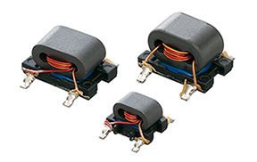
Impedance mismatch in a circuit results in energy being reflected back to the source, reducing the amount of power available to the load and possibly causing damage to the power source. Matching the output impedance of the power source to the input impedance of an electrical load maximizes power transfer from source to load. By matching the impedance of the source and load, circuit designers protect the power source from reflected energy and optimize circuit efficiency.
A symmetrical balanced line has two conductors having equal current in opposite (differential) directions. Twisted pair cable and ribbon cable are examples of balanced line cables. An asymmetrical unbalanced (single-ended) line has one conductor connected to ground, such as coaxial cable.
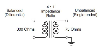
When a balanced source is to be isolated from an unbalanced load, the impedance matching transformer is referred to as a balun. If the impedance of the load matches that of the source, impedance matching is not required, and the balun has a 1:1 impedance ratio. When the load impedance is mismatched to the source in a 1:N impedance ratio, a 1:N impedance ratio transformer is required.
Quantifying non-ideal performance
The non-ideal nature of physical transformers results in the need for detailed specification documents when using these devices. The concluding FAQ of this three-part series provides a quantitative framework for specifying RF transformers.
References
Wirewound RF Transformers, Coilcraft CPS
LTCC Packaged Baluns, Murata Manufacturing
Coil-and-Wire Baluns, Murata Manufacturing
Using Baluns and RF Components for Impedance Matching
How RF Transformers Work and How They are Measured, Minicircuits, Inc.,




Leave a Reply