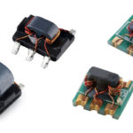
As discussed in Parts 1 & 2 of this FAQ series, RF transformers are complex devices and include parasitic resistances, inductances, and capacitances, which are non-linear and complex effects that compromise performance. Several fabrication methods including core-and-wire, low-temperature cofired ceramics (LTCC), and transmission line topologies have been developed to mitigate the impact of the various parasitics and help to optimize RF transformer characteristics for the needs of specific functions.
These transformers can be high-frequency or low-frequency (ranges include RF from 30kHz to 30MHz, VHF from 30MHz to 300MHz, and UHF from 300MHz to 3GHz and above), isolated or non-isolated, wide-band or narrow-band, and so on. Common RF transformer functions include:
- Impedance matching (sometimes called impedance transformation) to achieve maximum power transfer and to suppress undesired signal reflection.
- Voltage, current step-up or step-down.
- Efficiently coupling balanced to unbalanced circuits
- Providing DC isolation between circuits
- Injecting DC current into an RF path
- Enhancing common mode rejection (CMR)
- Ground isolation
- Filtering high frequency signals from a signal line
Depending on the needs of the application, important electrical performance specifications to consider when specifying RF transformers can include:
- Operating frequency range – measured in MHz is the frequency range over which the transformer meets all specifications, usually specified as the 3dB drop off, but also specified at 2dB and 1dB for higher-performance applications.
- Cutoff Frequency (sometimes referred to as the 3dB bandwidth) – measured in MHz and referenced to the mid-band insertion loss, the -3dB point is determined by the active inductance of the windings; the inter-winding and intra-winding capacitance dominates the high frequency cutoff.
- Insertion Loss – measured in dB, is the calculated value of 10*log (Po/Pi) where Po= Power Out and Pi=Power In. It is a result of the primary and secondary winding ohmic losses, as well as the dissipation within the core. As ohmic losses tend to be a function of frequency and temperature, the effective operating bandwidth of a transformer is limited by these factors.
- Inductance – measured in µH, sometimes with an explanatory footnote such as: “Inductance is for each winding, measured at 100kHz, 0.1Vrms, 0Adc on an Agilent/HP 4284A LCR meter or equivalent.”
- Amplitude unbalance (also referred to as Amplitude balance) – measured in dB, it is the absolute difference in signal amplitude between each output of a center-tapped RF transformer relative to the center tap.
- Phase unbalance (also referred to as Phase balance) – is measured in degrees.
- Impedance ratio – measured in dB, is determined by the square of the turns ratio.
- Common Mode Rejection Ratio – measured in dB, quantifies the suppression of DC interference between the transformer input and output.
- Rated DC current – measured in Amps, typically the continuous current rating, related to the DC resistance, lower DC resistance results in lower temperature rise at the maximum ambient operating temperature, and produces higher DC current rating.
- DCR – measured in Ohms, DC resistance (DCR) is specified as a maximum value
- Voltage Isolation – Can be a DC rating of an AC rating, depending on the application. RF transformers are most-often rated for DC voltage withstand for one minute such as 250Vdc primary-to-secondary, or 1,500Vdc primary-to-secondary, and so on. AC isolation, when used, is typically rated as a 60Hz or 50Hz RMS value, also for one minute. Common AC isolation ratings include 2.5kVRMS, 3.75kVRMS, or higher.
Other RF transformer specifications:
- Operating Temperature Range – like other components, RF transformers can be specified for operation over the consumer, industrial, automotive, rail transport, aero/space, and other standard temperature ranges.
- Shock and Vibration – can be specified as needed; standards include automotive, rail transport and mil/aero, and so on.
- Package Type – common examples include surface mount, flat pack, through hole or plug-in, connectorized, and waveguide assembly. In addition, screened packages can help to reduce electromagnetic and electrostatic interference from RF transformers.
- Packing Method – common examples include tape reel, tray, tube, and bulk pack.
- Center Tap Options – options include none, primary side only, secondary side only, and both sides.


Leave a Reply