
This is the first article in a three-part FAQ series on capacitors used in power-handling applications. In this first article, we will consider safety capacitors for filtering electromagnetic interference (EMI, also called radio frequency interference, RFI) on ac power lines, for antenna coupling, and for providing voltage isolation in DC/DC converters. Part two will look into “DC link, energy storage, and pulse power capacitors,” and the third and final article will consider “Capacitors for power converter output filtering.”
EMI filtering, for instance, in AC/DC power supplies or AC-mains powered motor drives, is the primary use of safety capacitors. More recently, capacitively-coupled DC/DC converter designs have appeared that use safety capacitors to provide input-to-output isolation. And safety MLCCs are finding use in antenna coupling applications.
Since capacitors in EMI filters are connected to ac power lines, these capacitors can fail due to over-voltages and transients. They are classified according to their use in the circuit. Capacitors connected line-to-line are called “X capacitors,” also called “line to neutral” capacitors. Those connected from line-to-ground are called “Y capacitors,” also called “line bypass capacitors.”
X capacitors are used for differential-mode EMI filtering. Y capacitors are used for common mode EMI filtering bypassing the interference from the wires to ground. Since safety capacitors are directly connected to the mains voltage, they can be subjected to voltage transients, power surges, overvoltage conditions, and other stresses resulting in device failure. They are designed for specific failure modes. Failure of X capacitors could result in a fire. X capacitors are designed to fail shorted, which causes a fuse or circuit breaker connected to the device to open, preventing the possibility of a fire.
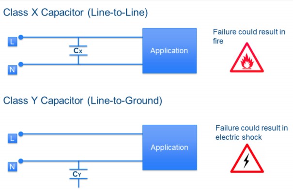
The shorting of a Y capacitor could present a fatal shock hazard for personnel using the equipment. As a result, Y capacitors are designed to fail open and prevent any possibility of a shock hazard. While the equipment is shut down by failure of an X capacitor and the subsequent tripping of an overcurrent protection device when a Y capacitor fails, the equipment could continue operating, but EMI filtering would be significantly reduced.
* 2 x Y2 or Y4 rated may bridge double or reinforced insulation when used in series.

Safety capacitor technologies
While it is theoretically possible to use several capacitor technologies to design X and Y safety capacitors, most commercial devices are either film capacitors or ceramic capacitors. There are cost and performance tradeoffs in selecting which Type of safety capacitor to use in specific applications.
Film capacitors may be the best choice when higher capacitance values are needed. Film capacitors cost more but offer self-healing enabling the device can recover from a dielectric breakdown with only a small reduction in capacitance. The capacitance and dissipation factor of film capacitors are stable across a wide temperature range suited to industrial applications.
Ceramic safety capacitors are available in several formats, disc capacitors (both two-terminal the three-terminal) and multilayer ceramic capacitors (MLCCs). Safety MLCCs include X2 and X1/Y2 devices rated for 250Vrms and are available in Class I NPO (COG) and Class II X7R dielectrics. In addition, some safety MLCCs are designed specifically for space-sensitive applications such as antenna coupling.
Some safety MLCCs are available with special terminations to accommodate the harsh automotive environment. For example, Murata offers the KCA series Type MF safety standard certified metal terminal type multilayer ceramic capacitors. This product has a distance between terminals of 4 mm or more and is intended mainly for use in onboard chargers, inverters, DC/DC converters, and other equipment in electric vehicles.

Leaded ceramic safety capacitors offer the highest dielectric rating and pulse capabilities. They are available in X1/Y1 safety classification and can handle up to 10kV pulses. They tend to have lower capacitance ratings than film capacitors, limiting their use in some applications. Ceramic devices are lower cost compared with film capacitors.
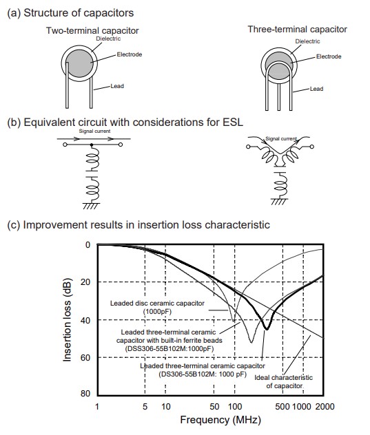
Three-terminal ceramic capacitors are available in which the shape of the lead terminals is modified to improve the high-frequency characteristics compared with two-terminal devices. One lead in a three-terminal capacitor has two connections. As a result, the residual inductance in series with the capacitance is lower, and the insertion loss is improved compared with two-terminal capacitors.
Safety capacitor standards
Because a shorted Y capacitor could lead to the danger of an electric shock, Y capacitors are held to a higher operating standard than X capacitors. During the certification process, two key tests performed are the impulse and endurance tests. These are done to verify that the X/Y capacitor can withstand ten impulses of alternating polarity, followed by a 1000-hour endurance AC life test. After completing these two tests, the capacitors must still perform reliably in the circuit under AC voltage conditions. These tests are part of the IEC 384-14 certification requirements.
EMI/RFI suppression capacitors must be designed to continue to perform satisfactorily after being subjected to this testing process and continue to meet the limits of EMC directive EN 50081. EMI/RFI capacitors must comply with the safety and inflammability requirements of international safety standards, such as the following:
- Europe: EN 60384-14
- USA: UL 60384-14, UL 1283
- Canada: CAN/CSA-E60384-14, CSA C22.2, No.8
- China: CQC (GB/T 6346.14-2015 or IEC 60384-14)
A design consideration when using X capacitors is the need to automatically discharge the capacitor upon loss of power to the power converter to comply with safety standards. Several suppliers offer integrated circuits that can be placed in series with bleed resistors (also called discharge resistors) that automatically discharge the energy in the X capacitor when the mains voltage is disconnected, diverting the energy away from the exposed AC plug and protecting equipment users.
Capacitive isolation for dc/dc converters
Capacitive isolation is most often associated with replacing optocouplers or transformers when transmitting data across an isolation barrier. It is not usually associated with power isolation. Helix Semiconductors has recently developed a technique that uses capacitors to provide voltage isolation in DC/DC converters.
The company offers three MxC 200 DC-DC TL (Transformerless Isolation) evaluation board (EVB) configurations: 10W 48V to isolated unregulated 12V output, 3W 6V to isolated unregulated 6V output, and 5W 48V to isolated unregulated ±12V and regulated 5V output. Each evaluation board is self-contained and ready for use.
For example, the MxC 270-EB-1 48V to 12V Output TL EVB is a standalone isolated 4:1 step-down 10W voltage reducer. A 4W configuration is also available using less expensive and smaller components.
Isolation is provided via the isolation barrier capacitors. Different types of capacitors are to be used depending on the required equipment safety classification. The 1.5KV capacitors used for 10W operation are not Y1/Y2 safety rated. Safety-rated film capacitors can be substituted as required. The 4W TL EVB configuration uses Y2 safety-rated MLCC capacitors.
The next article in this three-part series will consider “DC link, energy storage, and pulse power capacitors,” while the third article will focus on “Capacitors for power converter output filtering.”
References:
3-Terminal Capacitor Structure, Murata
12 Things to Know about Preventing Overloads with Safety Capacitors, Vishay Intertechnology
900 Series Safety Disc Capacitors, Kemet
Safety Certified MLCC Capacitors, Knowles Capacitors
MxC™ 200 TL EVB Manual, Helix Semiconductors
Leave a Reply