
Several safety features now found in gate driver integrated circuits make it easier for automotive system designs to get ASIL certification.
David Divins • Infineon Technologies
The Automotive Safety Integrity Level (ASIL) is a risk classification system defined by the ISO 26262 standard for the functional safety of road vehicles. There are four ASIL safety levels identified by ISO 26262—A, B, C, and D. ASIL A is the lowest level while ASIL D represents the highest level of automotive hazard. Systems like airbags, anti-lock brakes, and power steering must have an ASIL-D grade because the risks associated with their failure are greatest. Less critical systems are specified for lower levels.
ASIL certification is awarded at the system (or subsystem) level and not at the component level. But the number and type of safety features included in a component can help simplify the certification process for equipment manufacturers.
A typical application for a gate-driver IC is in the power switching of an electric vehicle’s traction motor. These switching devices are typically either insulated gate bipolar transistors (IGBT) or silicon carbide (SiC) transistors. Functions of the gate driver in this application include:
Amplification: The gate driver amplifies the low-voltage control signals from a microcontroller (MCU) to the higher voltage levels necessary to drive the power switching devices.
Isolation: A gate driver protects the low-voltage MCU from the much higher (and potentially damaging) voltages on the switching side.
Safety: In addition to protecting the MCU, a gate driver IC must include safety features to protect the overall system and hence its users. In an automobile these are the driver and vehicle passengers.
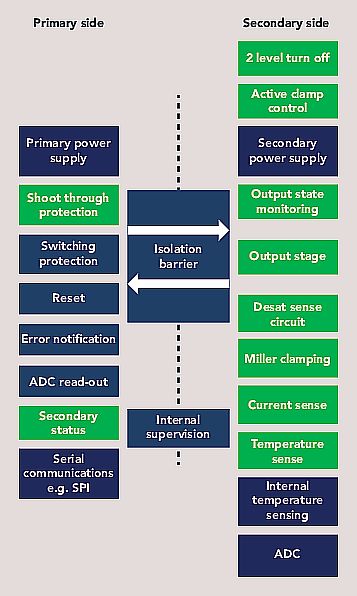
When it is part of an ASIL-compliant automotive system, a gate driver must accomplish three key objectives. First, it must be able to continuously self-monitor (to ensure it is operating correctly) and provide feedback in the event of failure. Apart from power-up monitoring, other desirable features include testing for communications across the isolation barrier, running a register memory test (e.g., parity check), doing an oscillator frequency check, measuring internal chip temperature, and implement a life sign watch dog function.
Second, the gate driver must continuously monitor the switching of the power semiconductor device. This action requires a combination of dynamic gate-voltage monitoring (during voltage transitions) and static gate-voltage sensing (at steady state). Power supply monitoring should include checks on all primary and secondary power supply rails including under- and overvoltage detection and also a test for a zero-volt connection reference for both the primary and secondary side (to ensure return paths are intact). Finally, the gate driver must continuously monitor and protect the semiconductor switching device itself. These actions can take place using the following safety checks.
Temperature, voltage and current monitoring
 The gate driver can be used to measure the temperature, voltage and/or current of the switching semiconductor. This information can then go to the MCU to determine if measured values are within the correct operating range. When driving a discrete device, a mirror of the emitter current can be used to drive a negative temperature coefficient thermistor (NTC) or a temperature-sensing diode. The generated voltage can then be used to create a digital representation of the device temperature. If driving a module, a gate driver can be used to read the temperature of the switching device directly from the internal temperature monitor while also watching the voltage levels the dc bus.
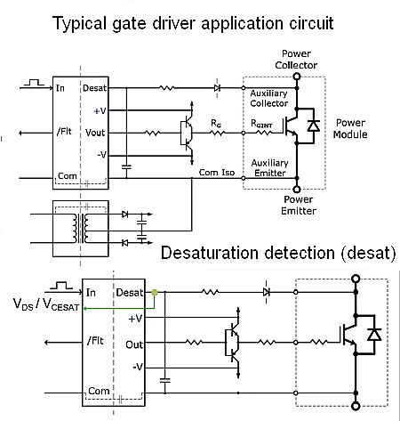
Desaturation detection (Desat) is a useful feature for monitoring the VDS of a SiC MOSFET or the VCESAT of an IGBT. However, for Desat to be effective, an IGBT must have a short circuit rating. Some SiC MOSFETs also specify a short-circuit rating, but Desat is not recommended in applications which use standard silicon MOSFETs because they switch too quickly for it to work.

During a desat event, the combination of short-circuit current and parasitic board inductance can cause a large overvoltage. This effect can be mitigated by using two-level turn-off to slow device switching action. This turn-off technique involves briefly putting the gate at an intermediate voltage before full turn-off, thus reducing the rate at which the short-circuit current drives the parasitic board inductance, thereby lowering the overvoltage.
The presence of noise in some environments can make Desat less effective. For example, capacitive loading on long motor cables can couple noise onto the Desat pin of the gate driver, causing false trips. False tripping can be mitigated by holding the Desat sense pin of the gate driver low for a short time interval (blanking time) until noise transients have died out. For longer-duration transients, additional filtering may be necessary.
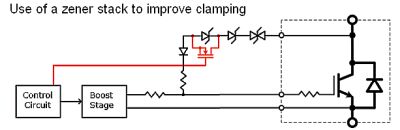 A Zener stack in series with a regular diode can be used to perform a clamping function in the event of a fast overvoltage. To further improve the noise margin, the clamping voltage can be modified to include an additional MOSFET whose gate connects to the control circuit.
The Miller capacitance at the gate of the switching device can cause ringing, resulting in the unwanted parasitic turn-on of the upper switching device in a half-bridge circuit. This turn-on can lead to EMI and heating problems and potentially even cause device failure. A Miller clamp at the output of a gate driver IC can prevent this problem. A Miller clamp lowers the output impedance of the gate driver if the parasitic ringing exceeds a certain level (detected using a sense node at the switch output). The lower output impedance reduces the amplitude of the ringing and makes a parasitic turn-on less probable.
Shoot-through protection
Shoot-through arises when both the high- and low-side devices in a half-bridge conduct simultaneously, leading to a short-circuit. To prevent this short-circuiting, a certain amount of “dead-time” (where both devices are off) should be programmed into the MCU.
While the use of monitoring and safety features in a gate driver IC can help reduce the chance of problems and mitigate their effects, these practices should never be used as substitutes for industry-standard double-pulse and corner (voltage, current and temperature) testing. Design engineers must decide which features their specific application demands. Challenges which designers must overcome include complex error handling, setup, and optimization of programmable features (many of which are power semiconductor-specific) and programming. Testing of power semiconductor performance under the full range of normal and fault operating conditions is always recommended.


Leave a Reply