
by Chris Francis
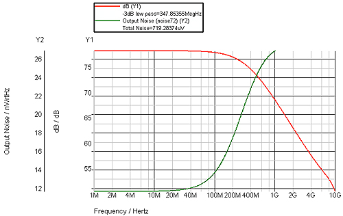
When dealing with high speed, low noise, non 50 ohm systems such as transimpedance amplifiers, a GaAsFET or HEMT can be a viable choice. On the face of it, devices such as the ATF35143 from Avago (previously known as Agilent) have suitable characteristics – low noise, low bias current and high bandwidth. Noise figure is 0.4dB at 2GHz and they have usable gain above 10GHz. They are quite power hungry taking 15mA when biased for best noise figure. By adding some gain and closing the feedback with a resistor to make a transimpedance amplifier you can have a respectable noise and transimpedance:
The schematic for that simulation is shown below:
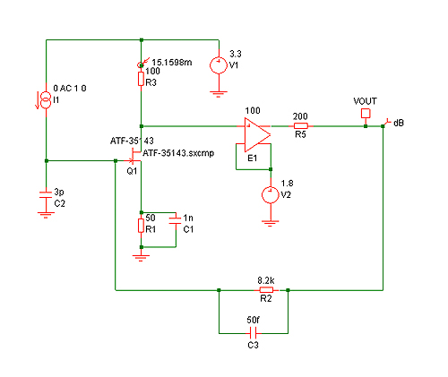
The voltage controlled voltage source (VCVS) E1 is used to represent an additional voltage gain of 100 (20dB) which could come from standard, high speed bipolar transistors. V2 controls the biasing. The drain current for these simulations is around 15mA. A current source and 3pF capacitor is used to represent a photodiode.
However, one disadvantage of the HEMT transistors is the high leakage current. It is specified at 10µA typical, 150uA worst case. While 10µA isn’t too bad, 150µA could be a problem with any transimpedance above a few kilo-ohms.
While a bipolar transistor isn’t always the first choice for a transimpedance amplifier with high transimpedance due to the base current, for low transimpedances they are viable. Rather than a conventional bipolar transistor, the SiGe:C silicon germanium carbon transistors from Infineon are worth looking at. For example the BFP640ESD has 0.65dB noise figure at 1.9GHz, and a transition frequency fT of 45GHz. While the noise figure is not as good as the HEMT, the SiGe:C does it at 6mA instead of 15mA for the HEMT figures. DC current gain is high at around 180 meaning it is viable in a transimpedance configuration provided the collector current isn’t too high. Current gain for conventional bipolar RF transistors is often quite a bit lower. Crucially, base-emitter leakage is 10µA maximum which compares well with the HEMT.
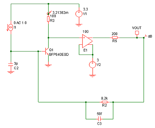
Substituting the SiGe:C in place of the HEMT in the previous schematic, with some biasing changes, gives the following results:
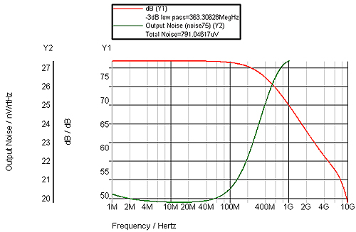
Bandwidth is almost identical, mainly because that is dictated by the feedback network (which would in reality be made using a capacitive T network so practical values can be used). The noise is a little higher but the SiGe:C transistor is only biased with 3mA rather than 15mA for the HEMT:
The BFP640ESD has ESD protection as the name suggests. There is a version without the ESD protection. The BFP640 is just one of quite a few SiGe:C transistors from Infineon. Usefully Infineon provide SPICE models for simulation which I find more useful than S Parameters when working with such designs.
Initially I had problems with the SPICE model at elevated temperature causing a “singular matrix”. This turned out to be a problem with model where VJC was 0.1152. A bit of searching came up with “The TNOM value of VJE, VJC and VJS must be greater than 0.4V to insure convergence for temperature analysis up to 200C”. This is a requirement of the Gummel-Poon SPICE model. Infineon support was helpful – coming up with a new model with a revised VJC greater than 0.4 and that is the model you will find on their web site (version 3 of the model). It is good too find a company taking modeling problems seriously. There are quite a few defective models on manufacturers’ web sites and all too often if you report a problem it is simply ignored or you get a pointless rely such as telling you where to download their models!
Leave a Reply