When correctly used, supercapacitors can support high power levels, high pulse power loads, and long-term back-up power needs. Understanding the nuances of supercapacitor specifications is the key to maximizing these performance capabilities.
There is some level of standardization for supercapacitor sizes, for example, a 10x30mm can supercapacitor is generally 10 Farads across the industry. Some suppliers offer it as an 11F or 12F device with different capacitance tolerances possibly, and this same trend spans in other can sizes as well, but that is often seen as a marketing strategy. What truly differs are the other electrical parameters such as DCL (leakage current) or ESR (equivalent series resistance) that directly impact performance in the use of the application. Those are not standard across the industry based on size or capacitance.
While specification documents for supercapacitors generally highlight the capacitance and voltage of the devices (and the resulting energy density), understanding the ESR is one of the critical factors related to long-term system design success. For example, while supercapacitor capacitance and ESR are both temperature-dependent, the temperature dependence of ESR is much greater than that of capacitance.
Supercapacitor ESR varies between models, series, and from manufacturer-to-manufacturer. In general, ESR decreases as capacitance increases. For example, AVX manufacturers special low ESR designed supercapacitors (SCC LE Series) that feature low ESR characteristics compared to their own standard series (SCC Series) or in the industry. These can be critical in application or for solutions that require multiple cells in series as ESR is additive. However, the sacrifice made to achieve that low ESR performance comes at the expense of DCL, as they are typically inversely proportional.
Capacitance is generally fairly stable from 25°C and up through the rated temperature range, but can drop by 25% or more at lower temperatures such as -40°C. High-performance supercapacitor designs can exhibit little capacitance change over the entire operating temperature range from -40°C and up.
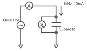
Supercapacitor ESR is more complex. It typically gets lower at higher temperature and higher at lower temperature. For some typical devices, the ESR at 85°C is half of the ESR at 25°C and the ESR at -40°C can be about 9 times of the ESR at 25°C. Even high-performance devices with little or no change in capacitance over the operating temperature range can exhibit 250% or greater change in ESR over the same temperature range.
Temperature, Voltage and Supercapacitor Lifetimes
It’s not only temperature that impacts supercapacitor performance; the combination of operating temperature and applied voltage is a significant consideration in determining the operating life of a supercapacitor. When considering combined temperature and applied voltage effects, ESR is an important factor.
Relatively low-temperature (e.g. 25°C) operation of supercapacitors reduces internal wearout mechanisms and the resulting increase in ESR. At higher temperatures, decreasing the applied voltage can help offset the detrimental impact of the higher temperature. Raising the applied voltage at lower temperatures can help offset increasing ESR.
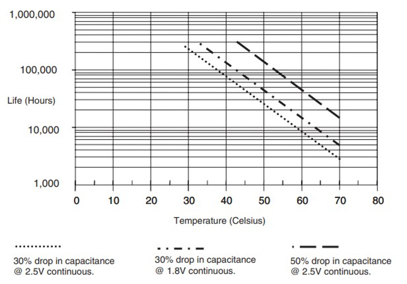
The plot below shows the time taken for capacitance to drop by 30% at 1.8V and 2.5V and by 50% at 2.5V for continuous operation at a given temperature. This can be used to estimate the operating life for specific applications where the minimum allowable capacitance value is known.
Charge and Discharge Characteristics
Losses measured during supercapacitor charging and discharging are related to the internal DC resistance of the device. This internal DC resistance (Ri) should not be confused with the ESR or internal AC resistance. ESR is much smaller than DC resistance. While ESR is useful when considering supercapacitor lifetimes, it is not relevant for calculatings inrush currents or other peak currents.
Voltage Balancing
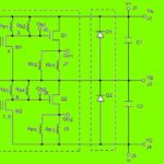
Voltage balancing is an important consideration when using multiple supercapacitors in series, such as in modules, to deliver higher voltages. It’s important to make sure that individual supercapacitor voltages do not exceed the maximum recommended working voltage. Exceeding that level results in degradation of ESR and device lifetime. Voltage imbalances result from differences in capacitance. Series connected devices act as a voltage divider so higher-capacitance devices experience a higher applied voltage. Since capacitance values can vary by +/-20%, voltage balancing becomes important in these applications.
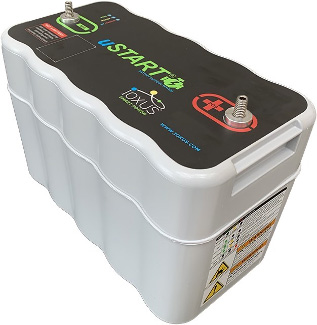
In passive voltage balancing voltage-dividing resistors are placed in parallel with each supercapacitor Active voltage balancing circuits control the voltages at the nodes of series connected devices, forcing them to be equal to a fixed reference voltage. While active voltage is more complex, it tends to be more efficient and more accurate.
Bringing it All Together, IEC/EN 62391–1
Supercapacitors from different manufacturers are generally not interchangeable. In addition, supercapacitor applications vary widely from high peak current/power uses to lower current/longer duration applications. This variety of needs is addressed by the test specifications and parameter requirements defined in IEC/EN 62391–1, Fixed electric double layer capacitors for use in electronic equipment. The standard defines four application classes, according to discharge current levels:
- Energy storage, mainly used for driving motors require a short time operation,
- Power, higher power demand for a long duration operation,
- Instantaneous power, for applications that requires relatively high current pulses or peak currents up to several hundreds of amps even with short operating times, and
- Memory backup.
References:
Murata Supercapacitor Technical Note
Eaton Supercapacitor Application Guidelines
IEC 62391-1:2015, Fixed electric double layer capacitors for use in electronic equipment
Skeleton Technologies, Ultracapacitor Voltage, Temperature and Lifetime
Wikipedia Supercapacitor



Leave a Reply