
Supercapacitors can deliver more: More power density, more Farads, more cycle life, and so on. But they also demand more complex solutions to realize optimal performance. Among the many design considerations are managing supercapacitor discharge, optimizing supercapacitor charging, and, in the case of series configurations of supercapacitor modules, providing effective voltage balancing between cells.
Properly sizing a supercapacitor solution for end of life due to its failure mechanisms can be a significant challenge. Supercapacitors are much more complex than conventional board-level capacitors, so in turn understanding how failure is influenced by voltage and temperature is never a “one size fits all” equation.
For example, the voltage discharge characteristics of supercapacitors can prevent the use of all available energy in certain classes of applications. When a supercapacitor is discharged under a constant power condition, voltage drops non-linearly as a result of the internal equivalent series resistance (ESR) of the device. When a supercapacitor is discharged at a constant current condition, voltage on the supercapacitor drops almost linearly over time.
The voltage drop is faster for higher power discharges. In high-current pulse applications, the resistive component can produce internal heating of the device, reducing the operating life of the supercapacitor. Supercapacitor lifetimes are mostly dependent on the evaporation of the electrolyte. Operating at elevated temperature or voltage can accelerate electrolyte evaporation.
Supercapacitor charging
Supercapacitor electrodes have a complex structure with numerous various-size pores in activated-carbon particles and an equally complex equivalent circuit model, so charging is not necessarily a simple matter. A supercapacitor charger typically needs to deliver high currents and operate over a wider voltage range than an “equivalent” battery charger. Depending on the application requirements, several charging methods can be used including:
- Constant current
- Constant voltage
- Constant current/constant voltage (CICV)
- Constant power
- Direct parallel connection to an energy source such as a battery or energy harvester
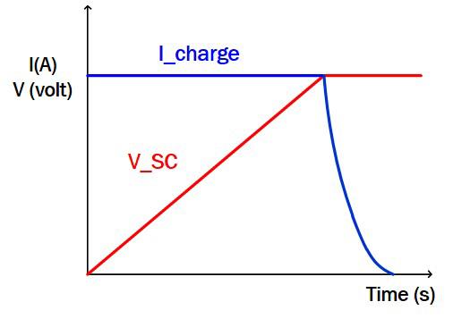
Constant current/constant voltage (CICV) is a commonly-used control method. At the beginning of the charge cycle, the charging device operates in constant current mode providing a constant current to the supercapacitor such that its voltage is linearly increasing. The supercapacitor is charged to a target voltage, at which time the constant voltage loop becomes active and accurately controls the supercapacitor charge level to be constant to avoid over charging.
In addition to charge controllers, IC chipsets used in conjunction with supercapacitors generally offer features grouped into:
- Current Control
- Balance Control & Overvoltage Protection
- Back-Up & Voltage Regulation
- Cell Balance Control
Many controller ICs come with built-in voltage regulation, monitoring, and multi-cell balancing when implementing a stack of supercapacitors. When using a stack or bank of supercapacitors, it is critical to have a balancing circuit on the supercapacitor stack that is purchased or an IC that provides active balancing.
Cell balancing
When supercapacitors are used in a series configuration to deliver higher voltages, voltage balancing becomes an issue. Since individual devices can have capacitance variations of +/-20%, the overall variation can be as much as 40% from one device to another and the higher capacitance devices will experience greater voltage stress, resulting in reduced operating lifetimes. Both passive and active approaches are used for cell balancing.
Voltage-dividing resistors in parallel with each supercapacitor are used in passive cell balancing configurations. Passive cell balancing is relatively inefficient and is generally recommended only for applications where supercapacitors are infrequently charged and discharged, or where cost is a major consideration. Some design guides recommend that balancing resistors be selected to support current flow 50X the anticipated worst-case leakage current of the supercapacitor.
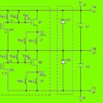
Active balance control can be implemented using an operational amplifier or using dedicated ICs. An operational amplifier solution costs more than a passive solution, but typically is less expensive than using a dedicated IC. Convergence speeds are comparable between the op amp and dedicated IC-based solutions.
Using dedicated ICs can provide a good solution for voltage balancing. These ICs are available in several configurations and from a number of manufactures including Advanced Linear Devices, AMS, Analog Devices, Dialog Semiconductor, O2 Micro, ROHM, Texas Instruments, and others. Typical configurations include:
- Balance control only
- Backup charge current control
- Balance control and overvoltage protection
- Balance control and backup voltage regulation
In the case of charge pump based system IC, necessary external parts are only ceramic capacitors. However, charge current is lower. In the case of a buck system IC or buck-boost system IC, charge current is high, but external components such as MOSFETs, power inductors, and so on are necessary.
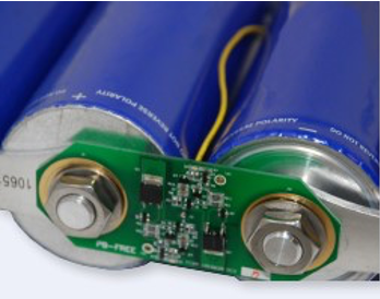
Maxwell Technologies offers a choice of standard solutions for active or passive cell balancing for use with its supercapacitors. The BKIT-MCINT board (pictured at the left) provides active cell balancing with a quiescent current of <60μA. The BKIT-MCIHT provides passive cell balancing with a balancing resistor.
References
Charge Control Methods for SuperCapacitors, AVX Corp.
Supercapacitor active cell balancing, Dialog Semiconductor
Supercapacitor Application Guidelines, Eaton
Supercapacitor integration kit with cell balancing, Maxwell
How to Charge Supercapacitor Banks, Renesas Electronics

Leave a Reply