• Skip to primary navigation
  • Skip to main content
  • Skip to primary sidebar
  • Skip to footer
  • Subscribe
  • Advertise

Power Electronic Tips

Power Electronic News, Editorial, Video and Resources

  • Products
    • Power Supplies
    • AC-DC
    • DC-DC
    • Battery Management
    • Capacitors
    • Magnetics
    • MOSFETS
    • Power Management
    • RF Power
    • Resistors
    • Transformers
    • Transistors
  • Applications
    • 5G
    • AI
    • Automotive
    • EV Engineering
    • LED Lighting
    • Industrial
    • IoT
    • Wireless
  • Learn
    • eBooks / Tech Tips
    • EE Training Days
    • FAQ
    • Learning Center
    • Tech Toolboxes
    • Webinars & Digital Events
  • Resources
    • Design Guide Library
    • Digital Issues
    • Engineering Diversity & Inclusion
    • LEAP Awards
    • Podcasts
    • White Papers
    • Design Fast
  • Video
    • EE Videos & Interviews
    • Teardown Videos
  • EE Forums
    • EDABoard.com
    • Electro-Tech-Online.com
  • Engineeering Training Days
  • Newsetter Subscription

Tamura explains how to pick a current transformer

July 26, 2018 By Lee Teschler

The subject of current transformers is pretty big when you’re talking about inverters and other kinds of power electronics. Tamura’s Craig Simpson went through some examples of that kind of technology in a recent video.

Tamura has been making current sensors for over 20 years and have developed quite a few different models of current sensors. They include Hall effect, open and closed loop sensors, and a new flux gate topology in current sensors.

Sensors with wide apertures are designed to handle PV and wind turbine applications and typically carry 2,000-A and 1,000-S ratings. One new model designed for the PV industry has a clip on it which gives the creepage and clearance necessary to meet a 1,500-V working voltage.

When you’re trying to pick a current sensor, the application engineer will want to know how much accuracy will be necessary. The open loop is about a 1% accuracy product. The closed loop is about 0.5% accuracy, so it offers a much better performance and of course a little bit higher cost to go along with that.

flux gate
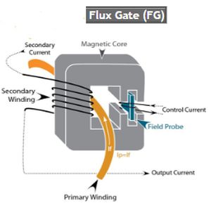
But then along with that is the new flux gate topology sensor which are all PCB mount devices but just have better performance. With a flux gate current sensor, the magnetic flux created by the primary current is balanced through a secondary coil using a magnetic probe device to provide a feedback and associated electronic circuitry to drive a compensating current in the secondary coil. The secondary (compensating) current is an exact (instantaneous) representation of the primary current and is converted to a voltage through an internal high precision resistor.

You may also like:

  • tamurasilicon-carbide gate drivers
    A look at IGBT and silicon-carbide gate drivers from Tamura

  • Tough terminology: Why working voltage matters in safety approvals
  • transformer
    Exotic magnetics could cut transformer weights from 35 tons to…
  • IGBT circuit
    How advanced IGBT gate drivers simplify high-voltage, high-current inverters

Filed Under: Featured, Transformers Tagged With: tamura

Primary Sidebar

Featured Contributions

Robust design for Variable Frequency Drives and starters

Meeting demand for hidden wearables via Schottky rectifiers

The case for vehicle 48 V power systems

GaN reliability milestones break through the silicon ceiling

Developing power architecture to support autonomous transportation

More Featured Contributions

EE LEARNING CENTER

EE Learning Center

EE TECH TOOLBOX

“ee
Tech Toolbox: 5G Technology
This Tech Toolbox covers the basics of 5G technology plus a story about how engineers designed and built a prototype DSL router mostly from old cellphone parts. Download this first 5G/wired/wireless communications Tech Toolbox to learn more!

EE ENGINEERING TRAINING DAYS

engineering
“power
EXPAND YOUR KNOWLEDGE AND STAY CONNECTED
Get the latest info on technologies, tools and strategies for EE professionals.
“bills

RSS Current EDABoard.com discussions

  • Diode recovery test Irrm timing.
  • Battery Deep Discharge – IC Workarounds?
  • The Analog Gods Hate Me
  • Safe Current and Power Density Limits in PCB Copper(in A/m² and W/m³) simulation
  • Why so few Phase shift full bridge controllers?

RSS Current Electro-Tech-Online.com Discussions

  • Wideband matching an electrically short bowtie antenna; 50 ohm, 434 MHz
  • The Analog Gods Hate Me
  • Simple LED Analog Clock Idea
  • PIC KIT 3 not able to program dsPIC
  • Parts required for a personal project

DesignFast

Component Selection Made Simple.

Try it Today
design fast globle

Footer

EE World Online Network

  • 5G Technology World
  • EE World Online
  • Engineers Garage
  • Analog IC Tips
  • Battery Power Tips
  • Connector Tips
  • DesignFast
  • EDA Board Forums
  • Electro Tech Online Forums
  • EV Engineering
  • Microcontroller Tips
  • Sensor Tips
  • Test and Measurement Tips

Power Electronic Tips

  • Subscribe to our newsletter
  • Advertise with us
  • Contact us
  • About us

Copyright © 2025 · WTWH Media LLC and its licensors. All rights reserved.
The material on this site may not be reproduced, distributed, transmitted, cached or otherwise used, except with the prior written permission of WTWH Media.

Privacy Policy