• Skip to primary navigation
  • Skip to main content
  • Skip to primary sidebar
  • Skip to footer
  • Subscribe
  • Advertise

Power Electronic Tips

Power Electronic News, Editorial, Video and Resources

  • Products
    • Power Supplies
    • AC-DC
    • DC-DC
    • Battery Management
    • Capacitors
    • Magnetics
    • MOSFETS
    • Power Management
    • RF Power
    • Resistors
    • Transformers
    • Transistors
  • Applications
    • 5G
    • AI
    • Automotive
    • EV Engineering
    • LED Lighting
    • Industrial
    • IoT
    • Wireless
  • Learn
    • eBooks / Tech Tips
    • EE Training Days
    • FAQ
    • Learning Center
    • Tech Toolboxes
    • Webinars & Digital Events
  • Resources
    • Design Guide Library
    • Digital Issues
    • Engineering Diversity & Inclusion
    • LEAP Awards
    • Podcasts
    • White Papers
    • Design Fast
  • Video
    • EE Videos & Interviews
    • Teardown Videos
  • EE Forums
    • EDABoard.com
    • Electro-Tech-Online.com
  • Engineeering Training Days
  • Newsetter Subscription

Teardown: Inside an electronic ice cube

September 26, 2016 By Lee Teschler

You might say an electronic ice cube makes for a cool teardown – literally. Here’s what’s inside cubes that lighten up drinks.

Lee Teschler
Executive Editor

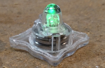
Transparent plastic cubes carrying built-in LEDs that flash are designed to plop into a drink glass like ice cubes. The idea, apparently, is that if you don’t get lit up from what you’re drinking the LEDs can do it instead. The cubes flash different patterns on the three LEDs they contain.

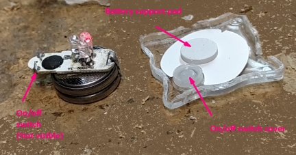
The cube also contains an on/off switch. We left our cube on continuously to see how long it would last. That time period turned out to be about a week with the LEDs growing continuously dimmer. And there was still enough juice left dimly light the LEDs when we cut into the cube for the teardown.

These cubes are often sold under the LiteCubes brand though several manufacturers make them. They are usually advertised as being comprised of FDA-approved cast acrylic packed with coolant gel. They are powered by two lithium-ion batteries and three LEDS, red, blue, and green.

cube internals before and after
With the cube intact, the “coolant gel” looks like crumpled cellophane. It turns into a glob of rubber cement-like stuff when air hits it.

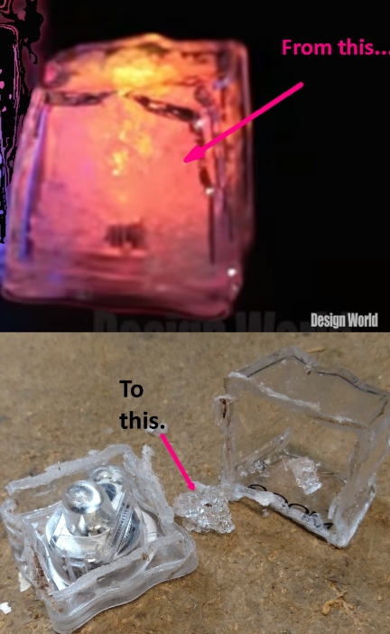
Perhaps the most interesting aspect of this item is the materials it uses rather than the electronics. Inside the cube appears to be cellophane which is there to scatter the LED light and give the cube more of an artistic look. But when we opened the cube and air got inside, the stuff that looked like cellophane – apparently the coolant gel mentioned in the marketing material — instantly collapsed into a small glob that looks a lot like rubber cement.

Once inside the cube, the construction is pretty straightforward. The base is actually two layers, one encasing the electronics. The rubber cement stuff is in a cavity formed by the top acrylic layer and the rest of the cube.

top cover off
Cutting off the cube acrylic leaves another layer of acrylic, visible here, over top the electronics.

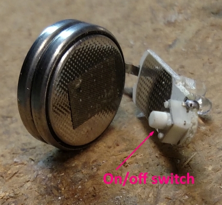
The circuit itself consists basically of two coin cells that are welded by a small strap going from the positive terminal to a small circuit board. The circuit board sits on the negative terminal and makes contact with it through what seems to be conductive adhesive. The circuit board contains the three LEDs, resistors that set the LED current, the chip that controls them, and an on/off switch.

battery and board
Visible here are the strap and solder connections between the PCB and lithium battery.
switch and board
Visible on the bottom of the PCB is the on/off switch.

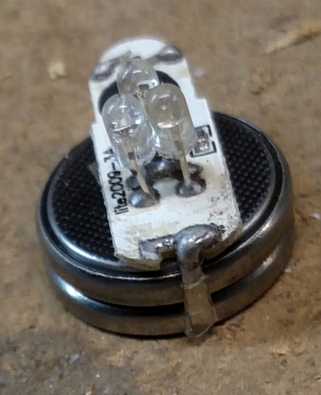
The chip, however, is not visible. It sits beneath a protective epoxy coating applied in a manner that’s called “chip on board.” Thus if we could look beneath the epoxy we’d see a die directly mounted on the PCB with the bond wires connected to copper traces. Of course, prying off the epoxy would destroy the chip in the process, and even looking at the die itself wouldn’t reveal much about how the IC works unless we bring in a scanning electron microscope.

electronics and base
Visible here are the base of the cube containing a battery support pad and on/off switch cover, and the PCB with LEDs and chip-on-board packaging.

A point to note, though, is that the device uses three LEDs instead of one tricolor LED. The reason is easy to understand: Tricolor LEDs tend to be made for applications in displays such as TV sets. They also tend to be much, much more expensive than LEDs that give off one kind of light. And because they tend to be used in displays where brightness is highly desirable, they also generally require a current in the range of hundreds of milliamps on up. So they are not really candidates for inexpensive plastic ice cubes that are sometimes given away as tchotchkes.

All in all, LiteCubes are an interesting example of what can be done with little more than a chip and a few LEDs.

Look here for the video version of this teardown.

Filed Under: LED Lighting

Primary Sidebar

Featured Contributions

Robust design for Variable Frequency Drives and starters

Meeting demand for hidden wearables via Schottky rectifiers

The case for vehicle 48 V power systems

GaN reliability milestones break through the silicon ceiling

Developing power architecture to support autonomous transportation

More Featured Contributions

EE LEARNING CENTER

EE Learning Center

EE TECH TOOLBOX

“ee
Tech Toolbox: 5G Technology
This Tech Toolbox covers the basics of 5G technology plus a story about how engineers designed and built a prototype DSL router mostly from old cellphone parts. Download this first 5G/wired/wireless communications Tech Toolbox to learn more!

EE ENGINEERING TRAINING DAYS

engineering
“power
EXPAND YOUR KNOWLEDGE AND STAY CONNECTED
Get the latest info on technologies, tools and strategies for EE professionals.
“bills

RSS Current EDABoard.com discussions

  • Testing 5kW Grid Tied inverter over 200-253VAC
  • Mean offset increase in post-layout simulation of clocked comparator
  • Getting different output for op amp circuit
  • dc-dc converter in series
  • Wireless microphone reviews

RSS Current Electro-Tech-Online.com Discussions

  • Back to the old BASIC days
  • using a RTC in SF basic
  • what's it's name
  • What is correct names for GOOD user friendly circuit drawing program?
  • Curved lines in PCB design

DesignFast

Component Selection Made Simple.

Try it Today
design fast globle

Footer

EE World Online Network

  • 5G Technology World
  • EE World Online
  • Engineers Garage
  • Analog IC Tips
  • Battery Power Tips
  • Connector Tips
  • DesignFast
  • EDA Board Forums
  • Electro Tech Online Forums
  • EV Engineering
  • Microcontroller Tips
  • Sensor Tips
  • Test and Measurement Tips

Power Electronic Tips

  • Subscribe to our newsletter
  • Advertise with us
  • Contact us
  • About us

Copyright © 2025 · WTWH Media LLC and its licensors. All rights reserved.
The material on this site may not be reproduced, distributed, transmitted, cached or otherwise used, except with the prior written permission of WTWH Media.

Privacy Policy