
by Leland Teschler, Executive Editor
A novel ac rectification and coil-driving scheme may characterize the electronics found in this widely used oral hygiene instrument.
The Philips Sonicare Elite series toothbrush is billed as generating over 31,000 brush strokes per minute thanks to “sonic motion” driving its brush. A teardown reveals what Philips is talking about in its marketing material: The brush head drive involves torsion bars positioned electromagnetically rather than by an electric motor.
Cut through the plastic handle of the Philips device and you’ll see a plastic frame holding a battery—a nickel-cadmium 1.2-V unit from Sanyo—the pickup coil in the base, which is used for inductive charging, and a massive electromagnet on an E-shaped frame. This electromagnet is used to move the brush head back and forth to get the brushing movement. The circuit board that contains the electronics solders onto this frame with seven pins making connections for the pickup coil, the battery and the brush-head drive coil.

Like most electric toothbrushes these days, the Philips Sonicare Elite employs wireless charging while it sits in a charging unit that doubles as a holder for the toothbrush. When we park the toothbrush in the holder and put a scope on the inductive pickup coil, we get a waveform that turns out to be at a frequency of about 100 kHz. So the base unit is generating a 100-kHz signal and the brush unit picks it up.
The base unit evidently contains a frequency converter that ups the mains frequency from 60 Hz to 100 kHz. Unfortunately, we couldn’t see the details of this circuitry because the base unit electronics are potted in some kind of epoxy.

On the toothbrush itself, the charging circuit is interesting in that there is extremely little to it. One can find teardowns of other brands of electric toothbrushes on the web that reveal what might be called conventional rectifier components: rectifier diodes and a capacitor or two for filtering, used to rectify the ac signal picked up by the charge coil into a dc signal that then goes to the rest of the components on the board. But that’s not at all what goes on in the Philips Sonicare brush.
Following the tiny traces on the circuit board in the handle shows that the pickup coil connects directly to a 24-pin chip. The chip doesn’t carry markings for any kind of commercially available device, so its functions can only be discerned by examining its connections. Chip markings indicate the IC comes from ams, or Austriamicrosystems.
There are no intervening components for rectification (or for anything else) between the wireless charging coil and this 24-pin IC, so the only conclusion can be that the chip does the rectifying.
But that’s not all it does. An examination of its connections shows it probably also contains an 8-bit processor. ams doesn’t make a processor chip, let alone one that contains some kind of ac rectifier. So we must conclude this is an ASIC of some kind that ams did for Philips.
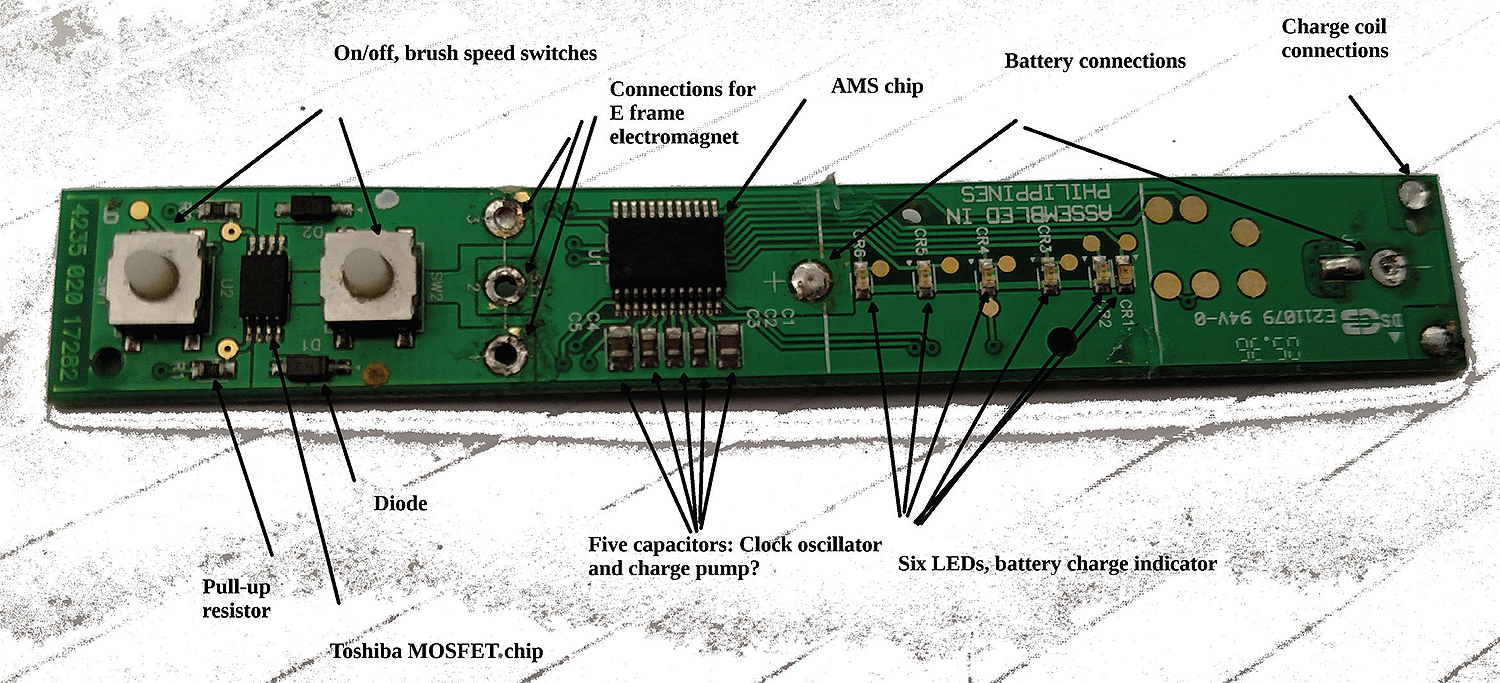
Teardowns of other electric toothbrush brands have found 4-bit, rather than 8-bit, processors handling the brush controls. But we counted what seem to be 10 I/O lines on the ams chip that would seem to indicate the use of at least an 8-bit controller: The board contains two momentary contact switches. One is a main turn-on switch, the other changes the speed of the brush if the operator desires. The ams processor chip has an input from both of them. Six pin connections go to six LEDs on the board that show the state of battery charging. Two more of the IC’s pins go to another chip that basically drives the brush back and forth, for a total of 10 outputs. Our guess: It is easier to manage 10 I/O connections with an 8-bit processor rather than a 4-bit device.
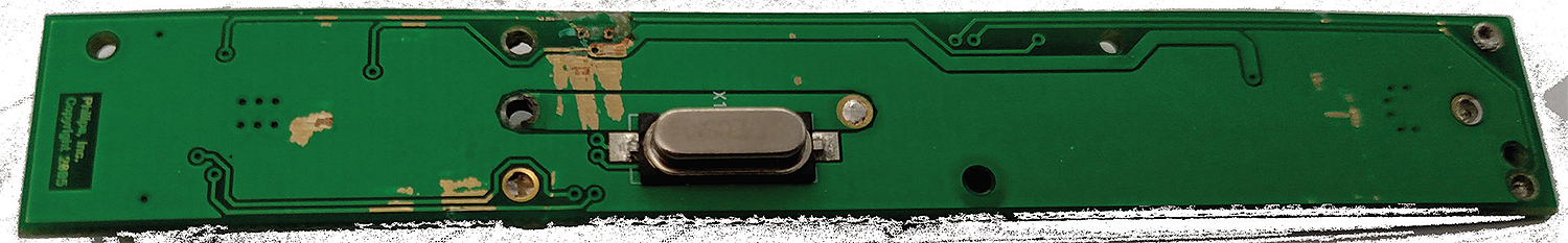
One thing is for sure: Regardless of its processing abilities, the ams chip is a clocked device. The presence of a crystal oscillator (again, with non-standard markings) on the backside of the board is a dead giveaway that we have a clocked circuit here.
Power conversion
The lack of markings on the ams chip makes the toothbrush charging scheme somewhat of a mystery. But there is a clue on the board in the form of five capacitors. It looks as though a couple of these capacitors might be part of the clock oscillator. But the other three don’t seem to have any function other than perhaps to work in the rectifier circuit somehow. Also, there are no inductors on the circuit board.

One ac-to-dc rectification scheme that uses capacitors only, no inductors, is a charge pump. It basically employs a network of diodes and charging or discharging capacitors to change an ac signal to a dc voltage. While the ac signal is positive, current flows through diodes and charges capacitors. When the ac signal goes negative, the diodes don’t conduct and the capacitors discharge. Multiple stages can be stacked to get better rectification.
The components found on the board are consistent with this approach. So it is plausible that this toothbrush uses some kind of a simple charge pump to get dc that charges up the battery.
Also, a look at the specs for the Sanyo battery reveals it slow-charges at 150 mA in about 16 hours. The Sonicare manual says the brush takes 24 hours to fully charge, so the charge current may be below 150 mA. That seems to be well within the level that an ASIC this size should be able to handle.

Perhaps the most interesting part of the circuit comes into play when the brush moves back and forth. With a push of the on/off switch, the processor turns on a circuit that generates an oscillating electric field. This happens using another chip, a Toshiba dual n-channel MOSFET. An output from the ams chip goes to the gate of each MOSFET. Each MOSFET output ties to one end of a coil driving the brush. There is a center tap on the coil that connects directly to the positive terminal of the battery.

So in operation, the processor drives one side of the coil, then the other, to generate an alternating magnetic field that vibrates the brush back and forth. We were unable to measure the frequency of that oscillating field, but one of the original patents for electric toothbrushes available online said it is in the range of 250 Hz.
The brush oscillation circuit contains two diodes. (We initially thought these had something to do with rectifying the 100-kHz charging waveform until we mapped out all the PCB traces.) These diodes are there to bleed off the inductive kick that arises when suddenly switching on big coils. The same kind of diodes can be found to reduce inductive kicks on circuits that switch electromechanical relays. Without the diodes, there’s a risk of destroying the MOSFETs. Completing the connection to the MOSFETs are two resistors serving as pull-down resistors for the MOSFET gates.
The oscillating field that appears at the end of the E-shaped frame interacts with the bottom of the brush head. And on the bottom of the brush head are two magnets, and they appear to be pretty strong magnets at that. We have no way of quantifying their magnetic fields, but they act as though they might be of the rare earth variety. This might also help explain why replacement brush heads for the Sonicare Elite series go for about $8 a piece or more as of this writing.

As the field changes, it basically pushes the magnets back and forth. The magnets in turn connect to the brush through three torsion bars which transmit the magnet motion to the brush itself.
And after a couple minutes of this 250-Hz oscillating action, the brush user has clean teeth.
References
Austriamicrosystems (ams)
www.ams.com/eng
Acoustic toothbrush patent: A lot of the circuit details on the Philips toothbrush resemble those described in this patent: www.google.com/patents/US20020092104.
Philips USA
www.usa.philips.com/c-m/consumer-products
Thanks for the clear and interesting analysis. Life is so interesting with all the modern things around us.
Hello,
Any advice for driving electric toothbrush coils with only two taps? I have a couple of students working on using electric toothbrushes to make music which means they need to control the frequency of the vibration. The have taken apart a couple and found them to be quite similar with only two taps on their coils. They have measured the 250hz on their scope which swings between positive and negative (about 5V in each direction). They have also found the gates on the dual channel mosfets and measured inputs on those gates. Since it is very hard to solder to the mosfets, the plan was to build their own dual mosfet circuit. Any suggestions would be greatly appreciated.
I’m trying to repurpose two functioning yet broken sonicares power systems for a lighting system for my bike and bike trailer to use during my frequent night rides. And a couple other similar batteries from other devices. I have the sonicare broken down but when I have another battery hooked with the one from the sonicare it won’t charge on the base. The secondary battery acts as the charger and its deleting the intended use I’m trying to make.
Going through a separation/ divorce and trying to learn whatever I can and actually complete a project. Any advice would be awesome!