
Xunwei Yu and Sungkeun Lim, Renesas Electronics Corporation
The USB-C interface is revolutionizing the way we charge our electronics devices. Its USB Type-C connector cable slides right into your smartphone or ultrabook no matter what orientation you use. Physically, the Type-C connector is both bidirectional (either end of the cable can be inserted into either device) and non-polarized (connector can go in either right side up or upside down). The connecting systems electrically figure out polarity as part of the negotiation process. In addition to data transfer, USB-C also supports bi-directional power flow at a much higher level. With a default 5V voltage, the USB-C port is capable of negotiating with a plugged-in device to raise the port voltage up to 20V, or another mutually agreed on voltage, and at an agreed to current level. The USB-C port’s maximum power delivery is 100W (20V at 5A), which is more than adequate to charge a laptop. With such appeal, it is easy to understand why electronic device makers are flocking to USB-C for their next generation products.
With the increasing use of USB power delivery (PD) and USB Type-C, the computer industry has significantly raised the performance requirement for the voltage regulator. Compared to conventional USB Type-A and USB Type-B fixed voltages, USB Type-C is a bidirectional port featuring a variable input and 5V to 20V output voltage range. Its adjustable output voltage allows notebooks and other mobile devices to use USB Type-C to replace the conventional AC/DC power adapter and USB Type-A and B terminals. Considering these advantages, some customers are designing in dual or multiple USB Type-C ports into their systems.
However, the current system architecture for dual or multiple USB Type-C ports is complicated and cannot meet many customer requirements. This article proposes a new USB-C system architecture using a buck-boost voltage regulator and battery charger. We will discuss how this architecture simplifies design and fully supports all USB-C functions. We’ll also describe how it can be applied to the adapter side to implement a programmable power supply (PPS), which outputs an adjustable voltage to match the USB-C variable input voltage.
A new architecture for USB Type-C
Figure 1 shows a new USB Type-C architecture that employs two bidirectional buck-boost (BB) voltage regulators and battery charger. It allows a system to charge its battery through USB Type-C ports, and it supports the fast charge function when two PD chargers are plugged into USB-C_1 and USB-C_2. This new architecture also supports full USB 3.1 On-The-Go (OTG) for both ports without additional complex port-control logic circuits or ICs.

Comparing Figure 1 and Figure 2, it’s easy to see that the current battery charger architecture requires more devices and complicated external circuitry to implement the same functions and performance level as the new USB Type-C battery charger architecture. Obviously, with the current battery charger system, every individual charger path requires a USB-PD controller to control two ASGATE and perform the charge function, which increases the design’s system cost. To implement 5V buck OTG, the OTG gate also needs a PD controller. Note that the current buck converter can only output a single fixed voltage. Figure 2 shows that if the 5V buck is adapted, designers can only output a fixed 5V, which doesn’t match the adjustable 5V up to 20V OTG output voltage required by many USB Type-C applications.
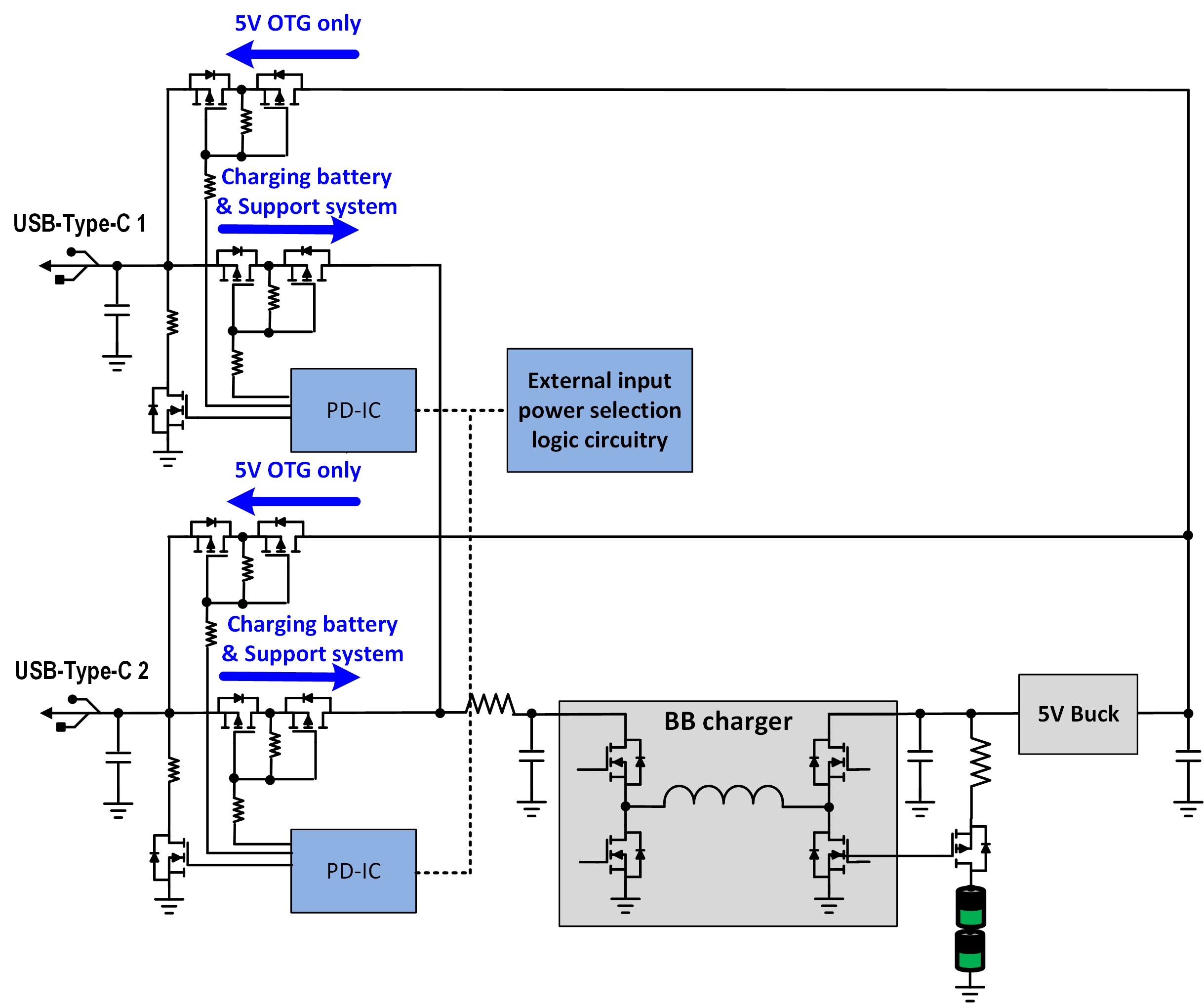
The new battery charging architecture overcomes all of these disadvantages. Figure 1 shows that two bidirectional buck-boost voltage regulators are in parallel to interface two USB Type-C ports to the battery charger. The system architecture is simplified, saving significant costs for customers because several components are eliminated, including individual PD controllers, ASGATE and OTG GATE. Most importantly, using fewer components does not degrade performance. For example, if the battery needs to be charged, power is delivered directly from the USB-C input to the battery charger. In addition, having two buck-boost voltage regulators in parallel provides even more options for customer applications.
For instance, two USB-C inputs with different power ratings can be applied for heavy charging the battery, which means the battery charge power is higher than the single USB-C input power. Figure 1 illustrates how this can be accomplished with one voltage regulator (set for USB-C high power rating) in the voltage loop to support a constant voltage (V0) for the battery charger input, while the other voltage regulator (set with a USB-C small power rating) is in the current loop to automatically deliver maximum power to the battery charger. In other words, there is no need to add external circuitry or logic to determine the different power rating operation of the two paralleled buck-boost voltage regulators.
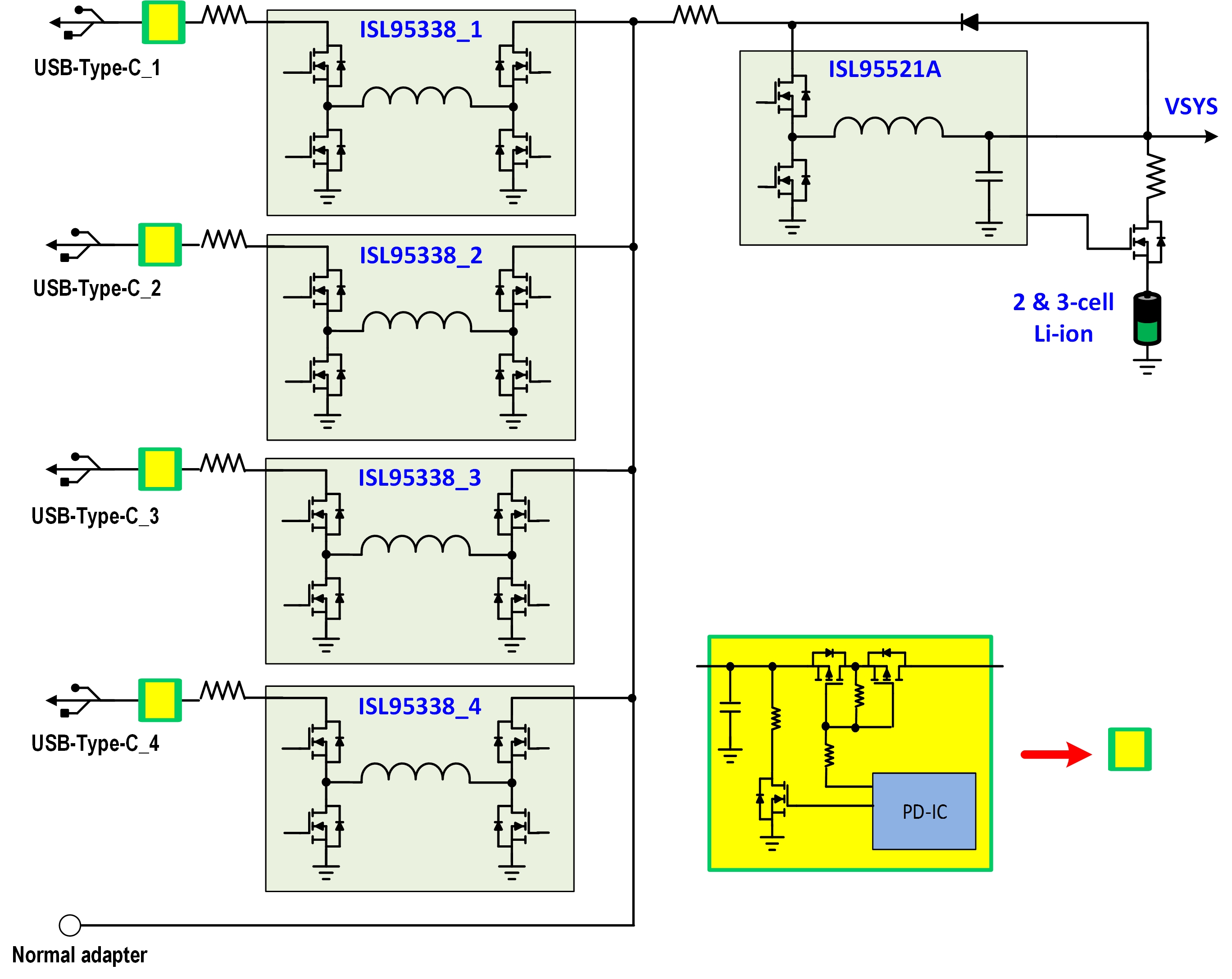
The control loop inside the voltage regulator can be automatically selected based on different power ratings to make full use of the input source. For the OTG function, battery power can be delivered through a diode with the voltage regulator transferring it to the USB-C output. This eliminates the need for the 5V buck and OTG gate, shown in Figure 2. Also, by using SMBus communication between the two voltage regulators, battery charger, and PD controller, the OTG voltage can be adjusted instead of using a fixed value. Figure 3 shows a high power fast charging application where the new USB-C battery charging architecture can be extended to parallel four buck-boost voltage regulators with one battery charger. Each USB-C port can operate individually as a sink or source. This architecture can also combine the conventional adapter as a power source for the system, without increasing BOM cost.
Programmable power supply solution
In conventional USB Type-A and USB Type-B applications, the input voltage is a fixed value, which brings new challenges to USB Type-C because USB-C can also accept variable input voltages. The solution is the programmable power supply (PPS) function, which allows the power supply’s output voltage and current to be programmed and adjusted in 20mV/50mA steps to optimize the power path. As shown in Figure 4, the ISL95338 USB-C buck-boost voltage regulator works well with PPS because it outputs an adjustable, bi-directional voltage using SMBus communication from the USB-PD controller.

Applying the ISL95338 in a multiport USB Type-C battery charging system enables a new, easy to use charging architecture. Compared to today’s currently available charging architecture, the new proposed USB-C architecture can be implemented at much lower cost, and achieve higher performance, faster charging and longer battery life. Furthermore, all USB Type-C requirements are in full compliance, including the ability to address PPS, one of the key USB additions required for future applications.
About the Authors
Xunwei Yu is an Applications Engineer with Renesas Electronics Battery & Optical Systems Division, and is located in the Research Triangle Park, North Carolina. He received his Ph.D. degrees from North Carolina State University.
Sungkeun Lim is an Applications Engineer with Renesas Electronics Battery & Optical Systems Division, and is located in the Research Triangle Park, North Carolina. He received his BSEE from Dong-A University, Busan, South Korea, and his MSEE and Ph.D. degrees from North Carolina State University.
Leave a Reply