System-level thermal design is equally important to the electrical specifications of board-mounted dc/dc converters. And the growing use of variations on a distributed power architecture (DPA) increases the complexity of thermal design. A single multiple-output ac/dc power supply is used to power the various loads in a conventional power architecture. The use of a centralized power supply also centralizes the thermal dissipation of the power conversion process, resulting in a straight forward thermal design.
In a DPA, a single-output ac/dc power supply produces a relative high distribution voltage (such as 12Vdc or 48Vdc), and multiple non-isolated step-down dc/dc converters power the lower-voltage loads. A DPA architecture spreads the thermal dissipation of the power conversion process throughout the system and complicates thermal design. The benefits of using a DPA can include a smaller overall solution sized, higher efficiency, and lower costs.
DC/DC converter selection considerations
As noted in the first FAQ in this series on “Specifying board-mounted dc/dc converters,” efficiency is often considered the most important specification. And efficiency has a major impact on thermal management. So, using high-efficiency board-mounted dc/dc converters is important. But it’s not quite that simple. Efficiency is typically specified at full load, and dc/dc converters are often derated and operated less than full power to improve system reliability. And systems often don’t operate using maximum power all of the time. It turns out that selecting the most efficient converter for a given application is not as simple as it first appears. Understanding system operating conditions enables designers to select board mounted dc/dc converters whose efficiency characteristics match the system’s needs.
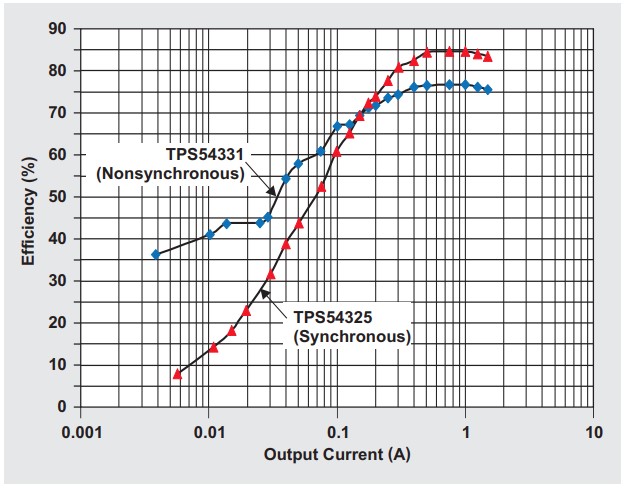
In addition, the buck converters used in DPAs are available in a variety of designs, each with various efficiency tradeoffs. For example, synchronous buck converters are more efficient at high loads than non-synchronous bucks. But the best choice is dependent on system operating characteristics. Non-synchronous bucks are typically more efficient under light load conditions compared with synchronous designs. In systems that spend a large proportion of time operating at low power levels and only occasionally demand peak power, a non-synchronous buck could provide higher overall operating efficiency. As a result of their simpler design, non-synchronous bucks cost less, and they are more reliable.
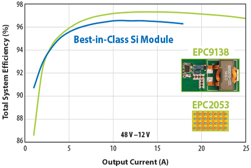
In systems that demand the highest efficiency, the use of emerging semiconductor materials such as gallium nitride (GaN) can provide increased efficiency and smaller size. GaN is a wide bandgap material with superior conductivity compared to traditional silicon. Compared with silicon devices, GaN transistors are smaller devices with lower capacitance for the same on resistance. Zero QRR also reduces losses at high frequency. The switching performance of GaN enables higher power density, higher frequency, higher switching precision, higher bus voltage, and less voltage overhead.
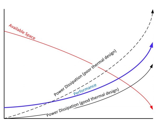
Not all board-mounted dc/dc converters are equal when it comes to thermal design and heat dissipation capabilities. Some are built on insulated metal substrates for enhanced thermal performance. Some include thermal vias for improved thermal conductivity, and some are beginning to use 3D power packaging using stacked, embedded, or planar components to achieve significant size reductions.
Reducing the physical size not only increases the power density; the reduced parasitics and smaller current loops mean that EMI can be kept under control even with Megahertz switching frequencies. The tradeoff is that thermal management can become much more complex. The overall dc-dc converter temperature performance relies heavily on how it is used in the final application.
System thermal mapping
Thermal management begins with measuring operating temperatures at the design stage with a thermal mapping of the system to identify hot spots and other areas of concern from a thermal standpoint. Thermal mapping is necessary to enable the correct thermal management system design for the specific operating environment. It helps to identify areas that need to be monitored (measured) during system operation.
If thermal imaging using an infrared (IR) camera indicates one or more hot spots on a PCB where there are higher than expected temperatures, that could indicate problems. If this is within the normal temperature range, the heat dissipation might still need improving. It’s important to consider neighboring components next to a higher heat location; they may experience longer-term degradation. To detect the hot-spots, a sufficient geometrical resolution is required. Only details which are well resolved by a sufficient number of pixels can be measured correctly. Therefore, high-resolution IR camera systems are a good choice for use during system development.
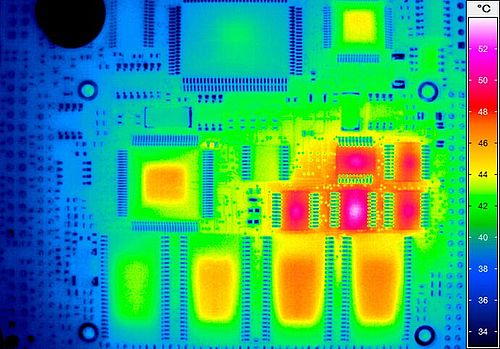
Unlike thermocouples or spot pyrometers, high-resolution IR cameras can take accurate temperature readings on both large targets and today’s micro-sized electronics. And thermal design is not a static situation. The thermal dissipation across the system often changes (sometimes rapidly) during changing system operating conditions. Some IR cameras can record high-speed data, with the sensitivity and spatial resolution needed to characterize fast thermal transients and steady state thermal conditions.
Monitoring thermal performance
While a built-in thermal shutdown feature is common for board-mounted dc/dc converters, it is often useful to continuously monitor the converters’ operating temperature. The following are two examples of the components available for thermal monitoring.
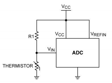
Thermistors are temperature-dependent resistors, usually made from conductive materials such as metal-oxide ceramics or polymers. The most common thermistors have a negative temperature coefficient (NTC) of resistance and are often referred to as NTCs. Signal conditioning is required to use NTCs. A thermistor is often used together with a fixed-value resistor in a voltage divider with the output digitized using an analog-to-digital converter (ADC).
Temperature sensor ICs take advantage of the thermal characteristics of silicon PN junctions. Because they are active circuits built using conventional semiconductor processes, they can take a variety of forms and include a variety of features (such as digital interfaces, ADC inputs, and fan-control functions). The operating temperature range for temperature sensor ICs extends as low as -55°C and as high as +125°C, with a few devices operating to an upper limit of around +150°C.
The first FAQ in this series looked at the complexities of specifying board-mounted dc/dc converters. Following this review of thermal management topics will be a discussion of “EMC/EMI design and the use of board-mount dc/dc converters.” The series will conclude with a look at the “basics of board-mounted dc/dc converter reliability.”
References
Efficiency of synchronous versus nonsynchronous buck converters, Texas Instruments
Thermal management handbook, Maxim Integrated
Thermal Optimisation of Components and Assemblies, InfraTec




Leave a Reply