
Current automotive quality standards may not be selective enough for power electronic devices that will run next-generation vehicles. Device makers are responding with their own more stringent test regimes.
Aleksandra Kozyczak, Lourdes Garcia | Infineon Technologies
Modern vehicles rely heavily on electronic systems. Each electronic component in these systems is a source of potential failure. Systemic failure modes in vehicles are extremely expensive for automakers because they can lead to vehicle recalls, service problems, and damage to brand and reputation.
To promote reliability, standards such as AEC-Q101 have been developed. But in the automotive world technology moves quickly, and any failure is unacceptable. So simply meeting these qualification standards is not enough.
Developers of automotive power electronics are particularly concerned with the reliability of MOSFETs and their common failure modes in the harsh automotive world. But there are processes used to ensure that MOSFETs significantly exceed the reliability requirements and mission profiles on which the AEC-Q101 is based.
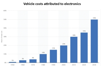
The overall electronics content is varied and includes a multitude of sensors, microcontrollers and other devices. However, MOSFETs are crucial devices in their role as electronic actuators, switching loads such as lamps, motors, injectors and more.
Current estimates are that the average car now uses around 60 power MOSFETs. If we assume a rate of just one defect-per-million (dpm), about sixty cars in every million manufactured (within certain confidence level) would fail solely because of a MOSFET. This defect level is not acceptable in the automotive industry.
To standardize the way in which discrete semiconductors are qualified for automotive applications, the Automotive Electronics Council (AEC) worked with several major semiconductor suppliers, including Infineon, to develop an industry-wide standard. The resulting AEC-Q101 Standard set requirements covering certain mission profiles and qualification definitions. These included batch sizes, pass/fail criteria, requirements to re-qualify after process changes, and specific test definitions (including applicability to different device/process types). The goal of this effort was to simulate the conditions found in vehicles and establish a reliability prediction that was accurate.
AEC-Q101 is a valuable standard that is mainly based on typical mission profiles. It is less effective with the untypical and stringent conditions increasingly common in vehicular applications. It is also a ‘one-time’ qualification that typically takes place at the end of the development cycle. Thus, it takes no account of long-term production process stability.
One major drawback of the standard is that its testing requirements involve relatively low sample sizes. For example, the standard requires just 77 devices from each of three lots to go through high-temperature reverse bias tests; ditto for temperature cycling tests. Statistically, the required test sample sizes aren’t always large enough to target a dpm rate below 10,000 at a 90% confidence level – not acceptable in modern automotive electronics.
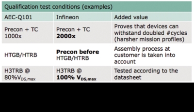
In addition, High Humidity High Temperature Reverse Bias (H3TRB) can take place at 80% of VDS,max. But Infineon tests at 100% of this value, thereby ensuring full coverage of the published datasheet specified values.
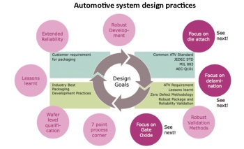
Infineon has over 40 years of experience in the automotive market and has shipped over five billion MOSFETs since 2010. This experience plus application know-how and stringent process control leads to minimal levels of random defects. A focus on three key areas (die attach, delamination and gate oxide) during development further boosts reliability. This holistic approach to automotive power MOSFET quality yields a dpm below 0.1 which is a benchmark in the industry.
Like all packaged semiconductor devices, MOSFETs suffer from mismatches of the coefficient of thermal expansion (CTE) of the mold compound, silicon die, lead frame and die pad during the thermal cycling expected in automotive applications. Simply put, as the MOSFET heats up rapidly and then cools, the different components expand and contract at slightly different rates. This action puts stress on dissimilar-metal interfaces that can eventually lead to device failure through lifted or broken bond wires and delamination.
To address this issue, Infineon developed a proprietary process that improves the adhesion between the molding compounds, silicon die, wirebonds, and the lead frame. This process involves growing hair-like dendrites on the die and lead frame that improve the adhesion by providing a mechanical attachment. Validation includes 1,000 thermal cycles, and devices undergo ultrasonic inspection at each stage to ensure there is no visible delamination.
In power devices, the thermal resistance between the semiconductor junction and the package (Rthjc) is a critical parameter. Designers rely upon it to ensure the package can conduct heat well enough to prevent any thermal build-up. However, delamination can also affect the attachment of the die to the die pad. Should the die become (partially) detached, then Rthjc will rise because of the impeded thermal path, raising the MOSFET junction temperature (Tj). As Tj rises, so will the on resistance of the MOSFET (Rdson), leading to higher power losses and the generation of more heat. As this thermal runaway continues, the most likely outcome is a device failure with an electrical overstress signature.
There are several ways of measuring Rthjc. Infineon uses the Delta VSD technique as it has proven to be effective and accurate. This technique relies on the fact that in a MOSFET the voltage across the intrinsic body diode (VSD) is linear with respect to Tj. After preconditioning, VSD is measured at 25°C and then measured again after the device is heated by a known reference current. A VSD reading lower than normal indicates Rthjc has risen, a clear indication of delamination.
Part average testing
Good design practices and stringent qualification testing ensures MOSFETs will be reliable. But there will always be variations within production batches. Most of these devices remain well within datasheet specification limits. However, a few may be weaker than others. Reliability studies indicate that semiconductor components having abnormal variations are more likely to have long-term quality and reliability problems. These outliers are more likely to fail in the field.
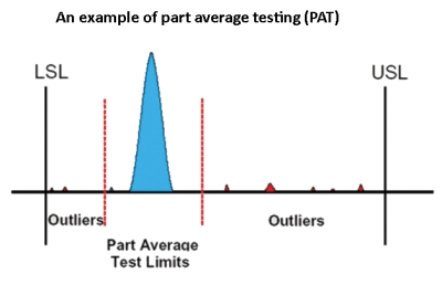
PAT is a dynamic test. It looks at the mean and standard deviation of measurement results as tests proceed. Outlier parts are considered those that passed the test but are not in a range determined by the mean and some multiple of the SD.
All in all, ever-more-stringent product qualification processes go beyond standards alone and assure automakers of reliable performance.
References
Infineon Technologies AG, MOSFETs, www.infineon.com/cms/en/product/power/mosfet/channel.html?channel=db3a304319c6f18c011a14e5341b25f1




[…] Tougher stress tests for automotive MOSFETs To promote reliability, standards such as AEC-Q101 have been developed. But in the automotive world technology moves quickly, and any failure is unacceptable. So simply meeting these qualification standards is not enough. […]