
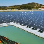
One of the advantages of photovoltaic (PV) energy is that it is inherently modular. Unlike many other energy sources, it allows the implementation of small-, medium- and large-scale generation systems, ranging from portable and rooftop systems to large multi-megawatt PV farms. System requirements, performance specifications, regulations, and even the economics behind the different system sizes, impose very different design constraints and requirements from a power electronics perspective, leading to distinct PV power converter classes and technologies.
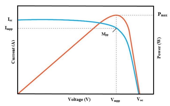
Among the power converters used with PV power systems are power optimizers, microinverters, string inverters (sometimes called central inverters), and battery chargers. An important consideration in many cases is the implementation of maximum power point tracking (MPPT). MPPT is a control algorithm that extracts the maximum power from PV panels and adapts in real time to changes in PV panel operation caused by changes in the environment such as the brightness of the sunlight, partial shading of the panel, the temperature of the panel, and so on. For example, a typical PV module produces power with maximum power voltage of around 17V at 25°C; it can drop to around 15V on a hot day in summer or rise to 18V on a cold winter day.
The EN 50530 European Standard provides a procedure for the measurement of the efficiency of MPPT of inverters. Both the static and dynamic MPPT efficiency are considered. Based on the static MPPT efficiency and conversion efficiency, the overall inverter efficiency is calculated. The dynamic MPPT efficiency is determined separately.
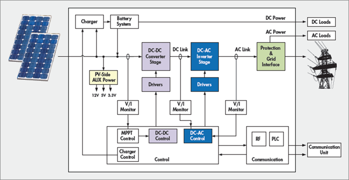
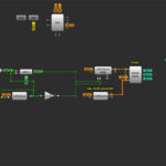
Central inverters are used to convert the DC power from strings of PV panels into AC power suitable for either off-grid use, such as in a building or microgrids, or for feeding into the utility grid. The MPPT function is generally implemented in the dc/dc converter control section of the inverter. In addition to MPPT capabilities, most central inverters include functions such as anti-islanding protection. PV inverters that connect to the utility grid are required to include anti-islanding.
Anti-islanding protection refers to the requirement that the inverter must turn off and completely disconnect from the grid in the event of a power failure on the grid. Anti-islanding prevents the inverter from feeding power into the grid and causing safety risks for utility workers and others who are expecting the grid to be unenergized.
Most central inverters also include some form of communication. This communication can be as simple as monitoring the inverter’s operational status, or it can include the ability to control the inverter’s operation remotely. In the case of so-called battery back-up inverters, there is also a battery charger to support the back-up battery system.
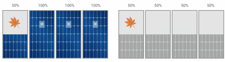
Traditional string or central solar inverters perform MPPT simultaneously for all the modules in the PV installation. In such systems, the same current, dictated by the inverter, flows through all modules in the string. Because different modules have different I-V curves and different maximum power points (due to manufacturing tolerance, partial shading, and so on), this architecture means some modules will be performing below their maximum power point, resulting in lower system efficiency.
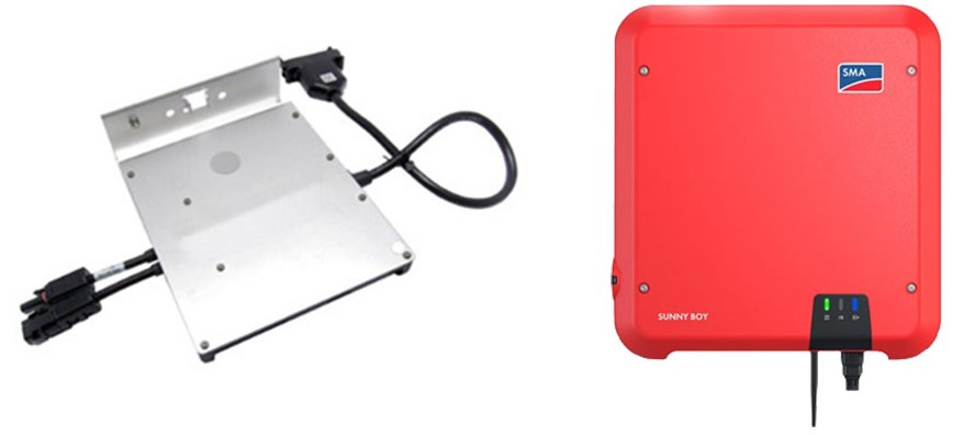
An alternative architecture uses a specialized dc/dc converter called a power optimizer to implement MPPT for each PV module in the installation. When the PV panels in an installation experience significantly varying conditions such as shading or physical orientation, power optimizers placed on each panel can be especially useful.
There is still a central or string inverter in a power optimizer architecture, but the need for MPPT is minimized or eliminated, simplifying inverter design and reducing inverter cost. An alternative to power optimizers is the use of microinverters. A microinverter combines a power optimizer and an inverter, eliminating the need for the central inverter.
In a string inverter architecture, all modules tend to perform down to the least efficient module level. For example, if one of the modules is heavily shaded and produces only 60% of its rated capacity, all the modules will be pulled down to 60%. If a power optimizer or microinverter architecture is used, only the heavily shaded module would be operating at 60%, the other modules would be operating at or near maximum power. That can result in significantly greater overall power generation.
Microinverters or dc optimizers in a distributed electronics architecture can produce a high-performance system but at a significantly higher cost, and the distributed approach can be more difficult to maintain compared with a central or string inverter. The advantages of the distributed electronics approach include:
- More electricity generated, depending on the characteristics of the installation site
- Operational flexibility for changing installation conditions (e.g., trees growing up or being taken out)
- Longer lifespan since microinverters and power optimizers generally carry the same 25-year warranty as the panel they are installed on, while central or string inverters usually have a warranty of 12 years or less.
- Panel level monitoring is easily implemented, enabling the identification of early panel wears out or other operational concerns.
- Easier system expansion since each panel comes with its own power electronics.
If the operational differences between the various panels are minimal, the advantage of distributed electronics such as power optimizers and microinverters will also be minimal. For example, in a typical roof-top installation, all the panels have the same orientation to the sun, and the panels can usually be installed to minimize shading. As a result, most residential rooftop PV installations employ central/string inverters for a more cost-effective solution, with only a small impact on performance.
Installation and commissioning of PV arrays
It is generally advisable to follow ASTM E3010 – 15(2019), Standard Practice for Installation, Commissioning, Operation, and Maintenance Process (ICOMP) of Photovoltaic Arrays. This practice details the minimum requirements for installation, commissioning, operations, and maintenance processes to ensure safe and reliable power generation for the photovoltaic system’s expected life. Specifically dealing with commercial photovoltaic installations, this practice covers a broad spectrum of designs and applications and is focused on the proper process to ensure quality. There are several considerations when using ASTM E3010 – 15(2019):
- This practice does not cover the electrical aspects of installation found in existing and national codes and does not replace or supersede electrical installation details covered by the same. The practice does address the integration of best practices into design and construction.
- The standard is divided into three key areas:
- Design, engineering, and construction of the PV plant. Systems should be designed with operation and maintenance (O&M) in mind. Further standards should be developed for building integrated or building-mounted systems, modules with embedded power electronics, lightweight, flexible modules, or other specific components.
- Commissioning, testing, and approval for power generation (Utility Witness Testing). Standards for owner acceptance will also be addressed.
- O&M of the PV plant, including performance monitoring, periodic inspection, preventive maintenance, and periodic re-commissioning.
General standards for PV installations
There are various standards regulating modes of photovoltaic system functioning, supervision, and standards advising planning and implementation of the systems, including safety regulations and standards for monitoring the performance of PV installations. Some of the more important standards include:
- Grid-Connected PV Systems
- IEC 60364-7-712, Electrical installations of buildings – Part 7-712: Requirements for special installations or locations – Solar photovoltaic (PV) power supply systems.
- IEC 61727, Photovoltaic (PV) systems – Characteristics of the utility interface
- IEC 61683, Photovoltaic systems – Power conditioners – Procedure for measuring efficiency.
- IEC 62093, Balance-of-system components for photovoltaic systems – Design qualification natural environments.
- IEC 62116, Test procedure of islanding prevention measures for utility-interconnected photovoltaic inverters.
- IEC 62446, Grid-connected photovoltaic systems – Minimum requirements for system documentation, commissioning tests, and inspection.
- UL1730, UL/IEC61730, safety standards
- UL7103, which is a recent standard for building integrated photovoltaics (BIPV).
- Monitoring of PV systems
- IEC 61724, Photovoltaic system performance monitoring – Guidelines for measurement, data exchange, and analysis.
- IEC 61850-7, Communication networks and systems for power utility automation – Part 7-420: Basic communication structure – Distributed energy resources logical nodes.
- IEC 60870, Telecontrol equipment and systems.
That concludes this three-part series on photovoltaic power generation. Part one reviewed “Trends in photovoltaic energy conversion.” Part two considered “PV module specifications and performance parameters.”
References
ASTM E3010 – 15(2019), ASTM International
Comparing Inverters, Enphase
Inverters, Green Power Systems
Maximum power point tracking, Wikipedia
Leave a Reply