by Asem Elshimi, Design Engineer, IoT Wireless Solutions, Silicon Labs
Confession: For the longest time, up to my senior year in electrical engineering school, I thought you could find a capacitor on its own. I had such a boundless imagination to think that you could find a circuit element that is purely capacitive in behavior and plug it into an op-amp, and you’ve got an integrator over the entire frequency domain. Isn’t this how we drew it in the textbooks? A capacitor always looked like a capacitor. There was nothing else.
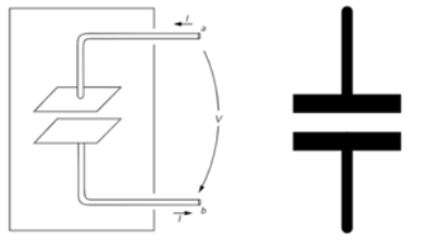
It turns out, this was just modeling; just an approximation. If the capacitive behavior of a circuit element in some frequency range is predictable, seasoned engineers will go ahead and put a capacitor symbol at that node (Figure 1). They don’t necessarily think it is only a capacitor. They know it is more complicated. But they would like to isolate one problem at a time and think of it as only a capacitor so they can focus on other parts of their design problem. Hence, textbooks teach engineering students how to solve circuit problems that have “ideal” capacitors, just so they are ready to do so in real life once they can assume that some element is actually a capacitor.
Let’s take a step back and look at what it means to say that some element is “capacitive.” What this means in electrical terms is that we expect the time-varying (ac) current across this element follows the rate of change of the current moving through this element. Hence the equation:
From this point of view, it almost sounds reasonable to assume that we can have a full-on capacitor. I mean, a capacitor that always behaves like a capacitor. It very merely stores electrical current in the form of charges, and then the voltage across it looks like an accumulation (integration) of that current. The reason we can’t see a problem by realizing an ideal capacitor from this electrical viewpoint is that it is too abstract — it hides all the information that shows why there is no guarantee that an element that behaves like a capacitor won’t do so across all different frequencies.
The information hidden here is electromagnetic rather than electric. The electromagnetic theory is always one step closer to nature than the electrical circuits theory. In other words, electrical circuits are nothing but an abstraction of Maxwell equations. While this abstraction is helpful in isolating and solving/designing complex circuits, it hides what sometimes could be vital information to the operation of such circuits. Fortunately, a good insight into electromagnetism fills that gap between electrical theory and reality.
Alright, enough with the esoteric views. Let’s go deeper. What is a capacitor in electromagnetic terms? Well, it comes in many forms, but for the sake of simplicity, let’s only discuss a parallel plate capacitor for the moment —everything I am going to state about parallel plate capacitors could be generalized to other geometries of capacitors. A capacitor consists of a pair of conducting plates from which two wires are brought out to suitable terminals. The plates are often separated by some dielectric material (Figure 2). Now, if we drive this structure with constant electrical voltage, (i.e., apply constant electric field potential to its terminals) uniform electric fields will form within the dielectric isolation. And the charges on one plate will be equal and opposite to the charges on the other plate. The fields arrive at this equilibrium state because the electric potential is constant, and hence, constant conductive currents cannot pass the isolation. There are no currents going through the structure at all (well, this is not entirely true, but let’s assume this for now.)

What happens when we start varying the applied potential, say, plug in a frequency generator with a 1 kHz signal? (1 kHz is a slow frequency in terms of wireless design nowadays, and we keep pursuing higher and higher frequencies to meet the demands of signal bandwidth under stringent FCC restrictions.) Now the potential is alternating; the once positively charged plate becomes negatively charged and vice versa for the other plate. The charge now sloshes back and forth between the upper and lower plates. This varying charge moves the dipoles of the dielectric insulator between the plates. The dipoles like to follow the polarity of the electric field applied on them. As you can imagine, the electric field is flipping its arrows up and down to follow the applied potential. The dipoles in the insulator follow the dance. This motion of dipoles creates a collective of electron motion that makes it look like electrons are traversing the insulators. They really aren’t (in dielectrics, electrons don’t have the freedom to move, they are kept tightly close to their atoms). But the collective dance of dipoles allows a transition of magnetic energy across the insulator that makes it appear like there was some electric conductive current in the middle. This is what the Ampere-Maxwell law tells us: Rotating magnetic fields can appear due to electric conductive current or due to varying electric potential across some dielectric.
As we can see, the dielectric dipoles only respond to the change of the electric field/potential, hence the conventional understanding in the electric circuits described above in which currents across capacitors follow the time derivative (change) of the voltage (potential) across the capacitor.
Even though in abstraction circuit theory and electromagnetism tell us the same thing about capacitors, electromagnetism tells us more about the underlying behavior. This story or context for how the fields interact inside the capacitor allows us also to understand why there are no “ideal” capacitors in real life.
Here is what it tells us: The varying electrical fields are generating dielectric currents that are as strong as the variation of the electric fields. That is to say, the currents aren’t so strong when the frequency is relatively low. This is why we started with the simple problem of low frequency — so that these dielectric currents aren’t very strong at the beginning. Now we want to see what is going to happen once these currents go higher. Before we do so, there is something worth noting about the Ampere-Maxwell law that we just mentioned: these currents, even though small in magnitude, are generating some rotating magnetic fields that surround them. When the frequency is low, these fields are low too, and this why we can safely ignore them. But what is going to happen once the frequency goes higher?
Let’s go back to the frequency generator and turn up the frequency knob (assuming it is an analog frequency generator, which I prefer anyway for purely aesthetic reasons.) As the frequency goes higher, the dielectric currents get more intense. Hence, their associated magnetic fields become prevalent. They are now intense enough to affect the equilibrium of fields. What do magnetic fields do? Well, anyone familiar with inductor properties knows that inductors have magnetic fields that oppose any change in the currents across them.
You may now know what we are about to discover. As we increase the frequency, the capacitor slowly diverges into an inductor. It is still a capacitor, but the higher the frequency, the more inductive it becomes. It has some rings of varying magnetic fields that surround its currents. The one interesting property of such rings is that they get tighter and stronger as we increase the frequency. To understand why, think of the inverse proportionality between wavelength (the diameter of the rings) and the frequency of variation.
As the magnetic field rings grow tighter and stronger, they induce more and more opposing currents. At some point, they start reversing the outside dielectric currents (the ones close to the outer edge of the parallel plates.) The big picture now is an electric field that is generating dielectric currents in the opposite direction of itself, due to the intermediate magnetic forces. If you wrap your mind around this image, you can see a capacitor in parallel with an inductor. Some of the currents (the inner lines of currents) follow the variation in the electric field and hence are capacitive. And the outer ones are following the variation in the magnetic field; in other words, they are generating varying electrical potential that is following the variation in currents. This is the equation of an inductor: V=L dI/dt.
Let’s take this experiment to an extreme and keep turning up the frequency knob. Allow the magnetic fields to get tighter and reverse more dielectric currents, until you get to a point where there is an equal number of currents going up and down. To an outside observer, the structure looks quiet. If you look at the parallel plate structure from far away, you don’t see any electric currents. But if you squint your eyes to see what is going on and realize that the currents are collectively canceling out. The structure is now self-resonating. It has reached such a peculiar state of equilibrium where electric and magnetic energies are equal. Hence the term, capacitor self-resonance.
As you increase the frequency above that self-resonance point, more lines are going in the opposite direction to the electrical potential than in the same direction. The structure now looks like an inductor.
Now we will never see a capacitor as only a capacitor again. We know it has an inductive personality, too, that is willing to dominate, but only waiting for the right frequency. Is this all? No, there is more that electromagnetics can tell us about parallel plate structures. For instance, we talked about the interchange between electric and magnetic energies in this structure. Whenever this interaction happens, some fields are going to escape the domain of the problem. That is to say; some energy will be radiated because fields cannot be confined to the boundaries of the problem. They can go too far and never come back. This portion of radiated energy can be seen as losses from the “ideal” capacitor point of view.
Losses are modeled as resistors. The value of the resistor could be chosen to fit into the equation. For the case of radiation, there is no actual resistor, but we can use a resistor to model the energy lost to radiation in our circuit problem. Other forms of losses come from the fact that the dielectric insulator is never perfect. Remember when we assumed that it doesn’t have any conductive currents between its plates? This is not true. It actually has some conductive currents traversing a highly resistive path of an imperfect insulator. This adds more losses.
If we want to include all the realities surrounding this parallel plate structure, let’s take a step back and see that connecting it to other circuit elements and forming a fun-to-solve electrical circuit requires some interconnects. The fields won’t magically appear on its plates. They must traverse some wires and some solder dots. This will introduce all sorts of lossy, inductive, and capacitive behaviors. This is the case if we are discussing a large electrical circuit. But what if the circuit we are tinkering with is actually on-chip and on the scale of few micro-meters? Up to really high frequencies (a few tens of GHz), we can ignore the inductive behavior of the interconnects. We are really only using very short metal interconnects with no soldering in between. This is the advantage of short distances in chip design, as shown in Figure 3 (die photo). But you already know that nothing in life comes for free. The price we have to pay for the behavior of such on-chip capacitors (or even inductors) is that (unlike the parallel plate problem we just examined), they now are operating at very close proximity to other capacitors and inductors.
Remember those fields that were radiated which we so easily dismissed as losses? Remember those very wide magnetic field rings that we said were negligible? This is no longer the case, when these fields are far from the structure we are examining, when they are too close to another structure and are interfering with its behavior. This situation is at its worst when the interference happens between elements that are supposed to operate at different frequencies. You start to see terrifying scenarios such as a power amplifier and voltage-controlled oscillator (PA-VCO) pulling in radio transceivers.

The complexity of electromagnetism is why we prefer to solve problems in terms of more abstract circuit theory. We can think high level and design and optimize. But at the base level, fundamentally, when we look at real devices, what we see is going to only follow electromagnetics strictly. If we are lucky, the rules of electromagnetics could be aligned with what circuits tell us. In my experience, this is generally not the case. We need always to process images of what the electromagnetic fields are doing in the back of our minds when we approach design — because it is safer to do so. And to be honest, because it is more fun to examine how forces of nature interact so intricately.
About the author
Asem Elshimi is an RFIC Design Engineer for IoT wireless solutions at Silicon Labs. He joined Silicon Labs in July 2018. Asem specializes in the areas of RF circuit design and electromagnetic structures design. He holds a Master of Science degree in Electrical and Computer Engineering from the University of California, Davis.


The report is very instructive and easy to understand.
Thank you very much for the information.