Stepper motors can be configured for unipolar or bipolar drive; each approach has different performance attributes and tradeoffs.
Despite their usefulness and suitability of stepper motors for precision positioning, especially in back-and-forth motion applications, one of the factors which delayed their widespread adoption was the challenge of providing the needed driver management. However, the introduction of ICs embedded with high levels of functionality has changed that. Many vendors offer stepper-motor driver ICs with various levels of features and capabilities.
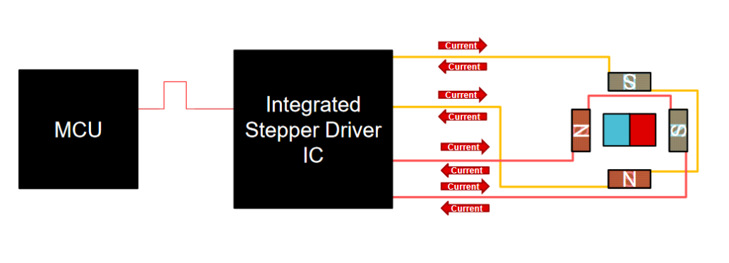
The role of the stepper driver is to act as the interface between the system microcontroller (MCU) or processor, which issues motion-related directives. It then implements these by directly managing the current and voltage to the motor (Figure 1) or driving external MOSFETs.
Basic drivers come with a range of rating combinations as general, single-IC drivers, which can deliver up to 1 or 2 A to the motor coils using on-chip MOSFETs. For stepper motors that require more current or voltage, a different stepper driver is used, which functions as a MOSFET driver and does not connect to the motor directly. The designer adds suitable external MOSFETs with ratings matched to the motor and project requirements. Some vendors offer broad families with a range of voltage- and current-drive capability as well as some stepper-motor controllers, which are rated for wider temperature ranges or for automotive applications (Figure 2).
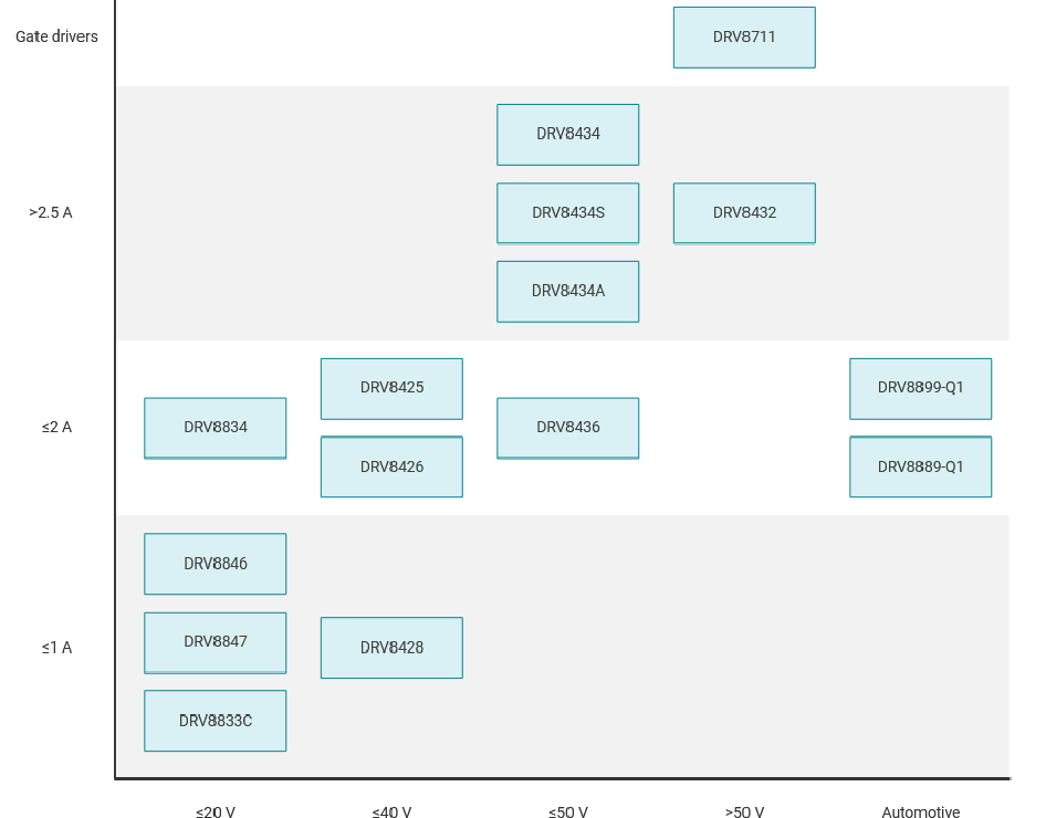
The differences among these drivers are not just their voltage- and current-drive ratings or ruggedness qualifications. It’s also a matter of feature set and functionality. Some applications need basic control, while others require added sophistication and potential for use as part of a more-complicated closed-loop system.
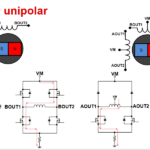
For example, the Texas Instruments DRV8847 is a basic dual H-bridge motor driver for applications such as lower-end industrial motors, home appliances, and POS (point of sale) printers, and which can be used unipolar and bipolar stepper motors (Figure 3).
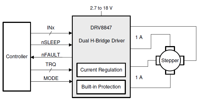
This tiny 16-lead IC communicates with the MCU via a simple four-wire PWM interface, and a two-wire I2C version is also available. The output stage of the driver has N-channel power MOSFETs configured as two full H-bridges to drive motor windings or four independent half bridges. (It can also be used to drive single or dual brushed DC motors as well as solenoids and relays since they all present similar loads.)
It operates from a single power supply ranging between 2.7 and 18 V while the integral bridge MOSFETs can deliver up to 1 or 2 A (rms) to the load depending on how it is set up. Internal protection functions are included for undervoltage-lockout, overcurrent protection on each FET, short circuit protection, open-load detection, and overtemperature; fault conditions are indicated by the status of a dedicated pin on the package.
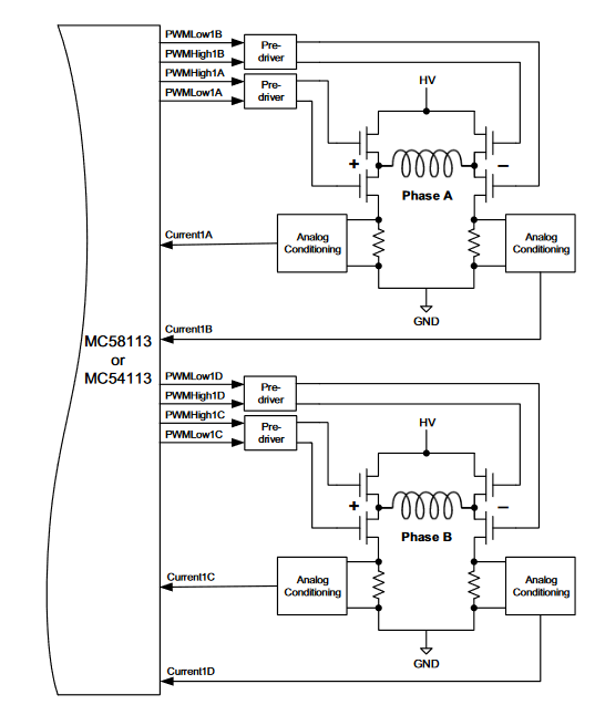
A more highly sophisticated stepper-motor driver is the 3.3 V MC54113 from Performance Motion Devices, part of their Magellan MC58113 family (Figure 4). Housed in a 100-pin TQFP package, this fully programmable device provides positioning, velocity, and torque control for two-phase stepper motors (again, also for brushless and brushed DC motors). It functions as the driver for the user-specified MOSFETs or power modules, as it does not directly drive the motor.
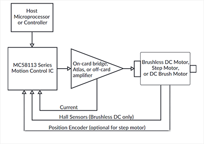
The MC54113 is connected to the host processor using a parallel bus, SPI (Serial Peripheral Interface), CANbus 2.0B, or even the classic RS232/485 serial interface. It incorporates various user-selectable motion-control profiling modes, including S-curve, trapezoidal, velocity contouring, and electronic gearing. It also supports the optional use of current-sensing or encoder feedback from the motor rotor. This allows it to implement PID servo-loop compensation and detect stalls, as well as velocity and acceleration feedforward compensation for crisper motor control (Figure 5). By doing all this, the MC54113 relieves the system processor of the considerable burden of implementing these features.
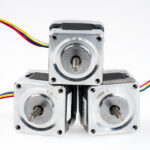
Stepper motors are widely used in applications ranging from small and low-cost printers to more-critical ones such as control positioning of powertrain functions in automobiles. Designers must balance various speed, torque, efficiency, size, and cost tradeoffs when choosing not only the specific motor but the way it will be configured and connected. Controller ICs offer different levels of management sophistication and algorithms as well as a choice of internal or external MOSFETs for powering the stepper coils, while vendors provide useful application notes and guides to selecting a suitable motor and controller pair and properly driving it.
Related EE World content
- Overcoming stepper motor design challenges in 3D printers
- Stepper motor driver IC simplifies low cost, power efficient designs with noiseless operation
- Basics of AC, DC, and EC electric motors (Part 2) — EC and stepper
- Thermal printers, Part 4: Components and circuitry
- Basics of motion-control profiles, Part 3: Implementations
- Basics of motion-control profiles, Part 2: Ramp profiles
- Basics of motion-control profiles, Part 1: Context
- Motor fundamentals and DC motors
- Basics of AC, DC, and EC electric motors, Part 1— AC and DC
External References
- Portescap (via Tech Briefs), “Bipolar and Unipolar Drives for Stepper Motors: A Comparison”
- Tech Explorations, “The difference between unipolar and bipolar stepper motors”
- Oriental Motor, “Wiring Basics: Unipolar vs Bipolar”
- Oriental Motor, “Unipolar/Bipolar Connections for 2-Phase Stepper Motors”
- Oyostepper, “Some differences between bipolar and unipolar stepper motor”
- Electrical4U, “Bipolar Stepper Motors: What is it?”
- Texas Instruments, “Drive unipolar stepper motors as bipolar stepper motors with a simple wiring reconfiguration”
- Texas Instruments, “Stepper Motor 1: Basics”
- Texas Instruments, “DRV8847 data sheet”
- Performance Motion Devices, “Magellan MC58113 Series Motion Control ICs”
- Performance Motion Devices, “Magellan Motion Control IC: MC58113 Electrical Specifications”


Leave a Reply