• Skip to primary navigation
  • Skip to main content
  • Skip to primary sidebar
  • Skip to footer
  • Subscribe
  • Advertise

Power Electronic Tips

Power Electronic News, Editorial, Video and Resources

  • Products
    • Power Supplies
    • AC-DC
    • DC-DC
    • Battery Management
    • Capacitors
    • Magnetics
    • MOSFETS
    • Power Management
    • RF Power
    • Resistors
    • Transformers
    • Transistors
  • Applications
    • 5G
    • AI
    • Automotive
    • EV Engineering
    • LED Lighting
    • Industrial
    • IoT
    • Wireless
  • Learn
    • eBooks / Tech Tips
    • EE Training Days
    • FAQ
    • Learning Center
    • Tech Toolboxes
    • Webinars & Digital Events
  • Resources
    • Design Guide Library
    • Digital Issues
    • Engineering Diversity & Inclusion
    • LEAP Awards
    • Podcasts
    • White Papers
    • Design Fast
  • Video
    • EE Videos & Interviews
    • Teardown Videos
  • EE Forums
    • EDABoard.com
    • Electro-Tech-Online.com
  • Engineeering Training Days
  • Newsetter Subscription

What are diodes? A quick refresher

August 13, 2018 By Janet Heath

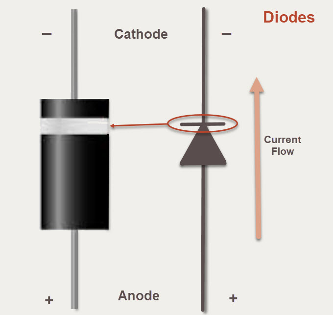
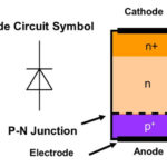
A diode is a passive component made with semiconductor materials (a chip) that conducts current flowing in one direction but does not conduct current flowing in the opposite direction. The symbol for a diode (to the right in Figure 1) looks something like an arrow pointing in the direction of the forward current. Current flows in one direction from the positive terminal (called the anode) to the negative terminal (called the cathode). An actual diode, shown to the left in Figure 1, is marked by a band on the cathode side. The band also corresponds to the symbol of the diode, indicating current flow.

diodes
Figure 1: A diode has polarity indicated as a band on the cathode (-) side. The electrical symbol for the diode has a corresponding line that also indicates the anode and thus the direction of current flow during forward voltage operation. (Image: author)

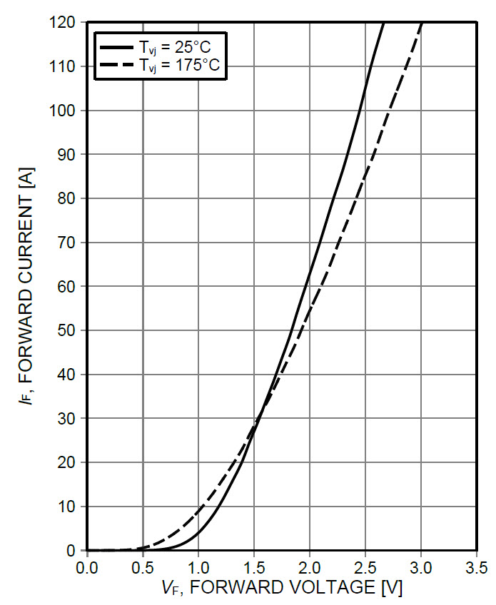
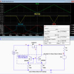
The Current-Voltage curve of a diode (Figure 2) shows the response of the diode as a function of current versus voltage. An ideal diode would not conduct any current if reverse-biased (experiencing negative voltage), but would conduct current fully (as if it were just a wire) if we were to apply a positive voltage across the diode. From the IV curve, you can tell that a real diode is non-linear. Diodes are not indestructible. If you reverse-biased a diode past its breakdown voltage, the diode will conduct current in the wrong direction. Some diodes, called Zener diodes, are specially designed with a low breakdown voltage that can be safely exceeded without damaging it. A high voltage Zener diode, also known as an avalanche diode, is meant to operate beyond the breakdown voltage. A diode reaches avalanche breakdown when the reverse-bias voltage exceeds the breakdown voltage. Avalanche is more commonly known as a catastrophic phenomenon.

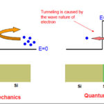
Speaking in terms of material science, avalanche concerns the reaction of electrons to the strength of the electric field at the PN junction of the semiconductor. Zener and avalanche diodes are different from regular diodes in that regular diodes are not designed to operate in reverse-bias mode. Thus, the I-V characteristics of Zener and avalanche diodes are meant to be used past the breakdown voltage.

Figure 2: The I-V curve from a datasheet for a general-purpose switching diode that shows the diode’s typical forward current as a function of forward voltage. (Source: Infineon datasheet for IDFW40E65D1E)

When a diode is reverse-biased to the breakdown voltage, current flows in the wrong direction but the diode is not broken; it’s just not working as a one-way device anymore. However, it is possible to break any diode. The diode’s datasheet will show the maximum ratings, including the peak level of reverse-bias voltage that the diode can withstand. Many diodes can withstand very large voltages before reaching breakdown. Zener diodes are often used for circuit protection. Zeners are useful for protection against biasing a circuit over its rated voltage (e.g., in a crowbar circuit), regulating voltage in a circuit (a.k.a. Zener diode shunt regulator),

Another type of diode is the Schottky diode. Schottky diodes have a semiconductor metal junction whereas a standard silicon diode has a semiconductor junction. A metal-semiconductor junction has metal in contact with the semiconductor material. (One of the main differences is that the metal semiconductor current will be higher at the same voltage bias than a diode with a PN junction. Additionally, with a metal-semiconductor junction, modulation and switching can be much faster.) One of the results of the metal-semiconductor junction is that the Schottky diode has a much quicker recovery time coming out of a reverse bias state. Schottky diodes, therefore, are used where recovery time at higher frequencies matter. Schottky diodes are used to clamp voltages (i.e., move the complete signal up or down in voltage level without changing the signal), for reverse current and discharge protection, and in switched mode power supplies.

diodes
Figure 3: The electrical symbols for a standard diode, Zener diode, Schottky Diode, and a Light-emitting Diode (LED). (Source: author)

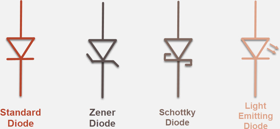
One diode that many people use every day is the Light Emitting Diode (LED). Technically, diodes are passive devices because like resistors, capacitors, inductors, and transformers, they do not control a signal (or current) using an electrical signal, even though it’s difficult to see them as passive when the LED releases visible energy as light. Nevertheless, the LED is another type of semiconductor-based diode that also conducts electricity when forward biased. The polarity of LEDs means that they will not shed light when the voltage is reverse-biased. LEDs used for indicators in circuits will have one longer leg that is the anode (+) and the shorter leg is the cathode (-).

Figure 4: For through-hole or other indicator LEDs that are used in circuits, the longer leg of the LED is the anode (+), the shorter leg is the cathode (-). (Image: VCC, Mouser Electronics)


You may also like:


  • What’s the difference between Shockley and Schottky diodes?
  • specialized diodes
    Specialized diodes, Part 2: Varactor, Gunn, and PIN diodes
  • specialized diodes
    Specialized diodes, Part 1: Tunnel, Zener/Avalanche, and Schottky diodes
  • MOSFET circuit
    A simple and inexpensive ideal-diode MOSFET circuit

Filed Under: diodes, FAQ, Featured, Power Components Tagged With: basics, FAQ, infineontechnologies, mouserelectronics

Reader Interactions

Comments

  1. Roger Tompsett says

    March 3, 2022 at 7:14 pm

    Nice diagrams but I think there may be an error in the text.
    The coloured band is at the cathode end of the diode as shown in the diagram, not the anode as stated in the text. In a rectifier, the (conventional) current flows out of the cathode, which makes it appear to be the positive terminal, but in fact it is at a slightly lower potential than the anode when the diode is conducting.

  2. Dennis Wickerham says

    April 18, 2023 at 4:34 pm

    Historically the diode was developed in a vacuum tube. The cathode emitted the cloud of electrons, which traveled from the cathode to the plate. This determined the direction of current flow.

    You have everything correct except the direction of the current flow. It’s
    backwards. So when explaining
    how a diode works current is going the wrong way.

Trackbacks

  1. Surface-mount small signal diodes available in ultra-compact DFN1006-2A package - Power Electronic Tips says:
    October 12, 2021 at 11:27 pm

    […] Intertechnology, Inc. introduced new surface-mount small signal diodes in the ultra-compact DFN1006-2A plastic package with wettable flanks. Designed to save space and […]

  2. What to look for in surge protection for power supplies - Power Electronic Tips says:
    March 28, 2023 at 3:23 pm

    […] components most commonly used in these circuits are transient voltage suppression diodes (TVS), metal-oxide varistors (MOV), and gas discharge tubes (GDT) […]

  3. What are the basic multilevel inverter topologies? - Power Electronic Tips says:
    March 26, 2025 at 5:28 am

    […] MLI, also known as a flying capacitor (FC) MLI, uses capacitors as clamping devices instead of diodes (Figure 3). This topology is designed to achieve multiple voltage levels by connecting capacitors […]

Primary Sidebar

Featured Contributions

Meeting demand for hidden wearables via Schottky rectifiers

The case for vehicle 48 V power systems

GaN reliability milestones break through the silicon ceiling

Developing power architecture to support autonomous transportation

What makes SiC tick?

More Featured Contributions

EE LEARNING CENTER

EE Learning Center

EE TECH TOOLBOX

“ee
Tech Toolbox: Internet of Things
Explore practical strategies for minimizing attack surfaces, managing memory efficiently, and securing firmware. Download now to ensure your IoT implementations remain secure, efficient, and future-ready.

EE ENGINEERING TRAINING DAYS

engineering
“power
EXPAND YOUR KNOWLEDGE AND STAY CONNECTED
Get the latest info on technologies, tools and strategies for EE professionals.
“bills

RSS Current EDABoard.com discussions

  • 12VAC to 12VDC 5A on 250ft 12AWG
  • Lightbox circuit help
  • Engineer's own PCB layout software guide?
  • LVS Mismatch Error in Simple Layout
  • Does mobility carrier ratio changes with Wn? (0.18um) inverter design

RSS Current Electro-Tech-Online.com Discussions

  • Actin group needed for effective PCB software tutorials
  • How to repair this plug in connector where wires came loose
  • Lightbox circuit
  • Fuel Auto Shutoff
  • Kawai KDP 80 Electronic Piano Dead

DesignFast

Component Selection Made Simple.

Try it Today
design fast globle

Footer

EE World Online Network

  • 5G Technology World
  • EE World Online
  • Engineers Garage
  • Analog IC Tips
  • Battery Power Tips
  • Connector Tips
  • DesignFast
  • EDA Board Forums
  • Electro Tech Online Forums
  • EV Engineering
  • Microcontroller Tips
  • Sensor Tips
  • Test and Measurement Tips

Power Electronic Tips

  • Subscribe to our newsletter
  • Advertise with us
  • Contact us
  • About us

Copyright © 2025 · WTWH Media LLC and its licensors. All rights reserved.
The material on this site may not be reproduced, distributed, transmitted, cached or otherwise used, except with the prior written permission of WTWH Media.

Privacy Policy