
In some applications, it can be useful to drain almost all of the energy of a single cell battery, well below the voltage where the battery is usually considered fully discharged or “dead.” That’s when a Joule Thief dc/dc converter can be attractive. The name implies that the dc/dc converter is stealing Joules of energy from the battery that are not available otherwise. It’s a very basic self-oscillating, unregulated voltage boosting circuit used for driving small loads such as single LEDs. It is also known as a blocking oscillator, Joule ringer, and vampire torch. While usually associated with driving a single LED, Joule Thief converters can also be used in small battery chargers, wall clocks, single solar cells, and other low-power applications where a low input voltage needs to be boosted.
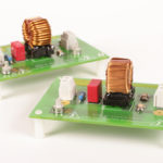
 Joule thief dc/dc converter driving an LED.
A rapidly switching NPN transistor is the basis of a Joule thief dc/dc converter. This circuit will typically switch at 5 to 40 kHz with about a 30% to 50% duty cycle when driving a small 3.0V LED from a 1.5V “AA” battery. As discussed below, the inductance of the transformer winding or inductor, depending on the specific design, determines the duty cycle.
There are several variations of this circuit, which can include a center-tapped inductor instead of the transformer. It is also possible to make a regulated Joule Thief using simple Zener diode regulation or closed-loop regulation. A linear regulator can be added to the output if a lower output ripple or more precise regulation is required.
Upon startup, current flows through the resistor (a typical value is 1kΩ ¼ W), the secondary winding of the transformer, and the base-emitter junction of the transistor, which causes the transistor to begin turning on, allowing current to flow through the transistor collector and the transformer primary winding.
With the transformer windings connected in opposing directions, a positive voltage is induced in the secondary winding, which turns on the transistor harder. This regenerative positive feedback mechanism rapidly turns the transistor on as hard as possible and places it in the saturation region. That makes the collector-emitter junction look almost like a short circuit (VCE will be as low as 0.1V, assuming the regenerative current in the base is high enough).
With the transistor in saturation, the primary winding is connected directly across the battery. The primary and secondary windings are usually the same number of windings, typically 12 to 25 turns, which results in low inductance. The inductance of the transformer windings determines the duty cycle of a Joule Thief. An increase in inductance generally increases the duty cycle. The current flowing through the primary winding increases at a rate determined by the ratio of the battery voltage and the (low) inductance of the transformer winding.
The NPN transistor has a gain that is not linear with VCE. Typically, these transistors need a larger base current to maintain saturation at low supply voltages (<0.75V) as the collector current increases. As a result, when the collector current rises to a critical level, the base current drive is not enough to maintain saturation, and the transistor begins to turn off. The transformer’s feedback rapidly drives the transistor hard off, and the cycle repeats, producing a pulsing output.
Joule Thief converters produce a high level of output ripple and are unregulated. However, they are surprisingly efficient. Because the transistor spends almost all the time either fully on or fully off, either the voltage or current through the transistor is zero during most of its operation, minimizing losses.
As shown, a Joule Thief can be a useful addition to an engineer’s circuit library. It enables the use of more of the energy in single-cell (1.5V) batteries compared with other topologies. It can be used in various applications where a low input voltage needs to be boosted (such as a single solar cell instead of a single cell battery). The basic circuit is noisy and lacks regulation, but additional components can be added to improve performance.


Leave a Reply