
IGBTs and IGCTs are four-layer devices that don’t look that different at first glance. But, when you ‘look under the hood’, you find that an insulated gate bipolar transistor (IGBT) and an integrated (sometimes called ‘insulated’) gate commutated thyristor (IGCT) aren’t that similar. A bipolar transistor forms the basis of an IGBT, while an IGCT is related to a gate turn off thyristor (GTO). IGBTs and IGCT were both developed for use in industrial applications. IGBTs can switch at 10+ kilohertz (kHz), while IGCTs are limited to a maximum of about 1 kHz.
This FAQ starts with a brief review of IGBT operation, digs into how an IGCT works and closes with a comparison of the two technologies.
IGBTs were developed to combine the simple gate drive requirements of power MOSFETs with the high current and low saturation voltage capabilities of bipolar transistors. They are a combination of a bipolar power switch controlled by an isolated-gate MOSFET in a single device (Figure 1). IGBTs are designed for fast and low-power capacitive switching, driving high voltage and high current loads. The isolated gate is a MOSFET structure, not a separate MOSFET. The MOSFET gate structure replaces the base of the bipolar transistor, and the resulting IGBT has an emitter, gate, and collector pins.
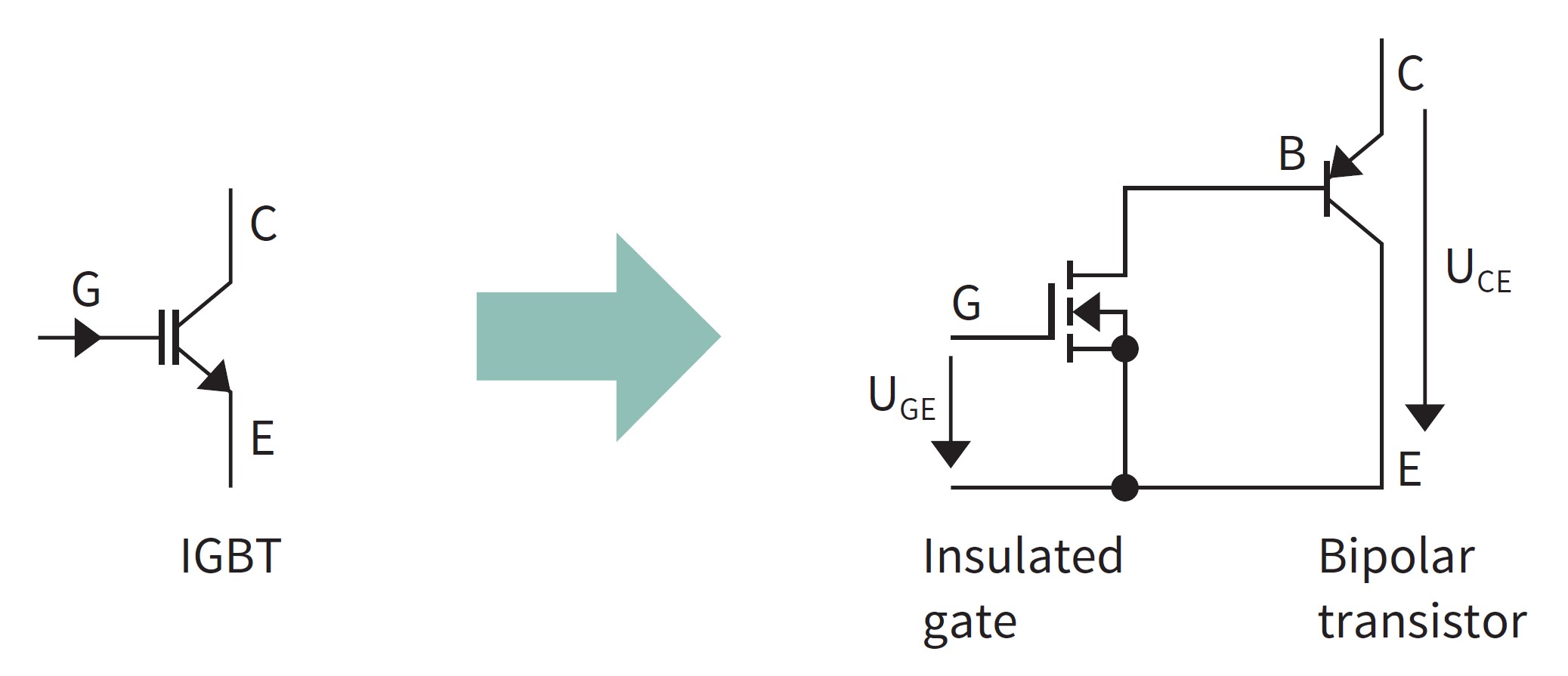
Basic IGBT operation is straightforward:
- A positive voltage (UGE) from gate to emitter turns on the MOSFET gate.
- That enables the voltage connected to the collector to drive base current through the bipolar transistor and the MOSFET;
- The bipolar transistor is turned on, and the load current flows through the IGBT.
- To turn off the IGBT, a voltage UGE ≤ 0 V is used to turn off the MOSFET, interrupting the base current, turning off the bipolar transistor, and the IGBT stops conducting current.
IGBTs conduct current in a single direction. Because of the capacitive nature of the MOSFET gate, the gate current only needs to charge the gate capacity to turn on the device. While the capacitive nature of the gate structure limits the amount of power needed to control an IGBT, the bipolar characteristics of the device limit its switching frequency to a maximum of about 30 kHz. However, resonant topologies that reduce the switching losses can enable IGBTs to switch at somewhat higher frequencies.
Unlike a power MOSFET, an IGBT does not have an inherent body or freewheeling diode. However, a diode is needed to protect the IGBT by providing a freewheeling path to prevent reverse current. Some IGBTs are available with an integrated diode; otherwise, a diode must be added to the circuit.
Adding an auxiliary emitter to reduce the influence of stray inductances in the gate circuit can improve IGBT switching performance (Figure 2). The auxiliary emitter does not carry load current; it reduces distortion resulting from inductive coupling, cleans up with switching waveform, and simplifies electromagnetic compatibility design.

IGBTs are used in medium- to high-power switching power supplies, renewable inverters, traction motor drives, induction heating, and similar applications, up to hundreds of kilowatts. Large IGBTs typically consist of many paralleled devices with blocking voltages up to 6,500 V capable of handling hundreds of amps. While IGBTs switch faster than IGCTs, they switch at lower frequencies than power MOSFETs. For power converters that need devices between 300V and 600V, IGBTs and MOSFETs can be used, depending on the application’s specific needs; below 600V, MOSFETs dominate, and above 600V, IGBTs dominate. Like IGBTs, IGCTs are fully controllable power switches used in self-commutated power converters.
IGCT basics
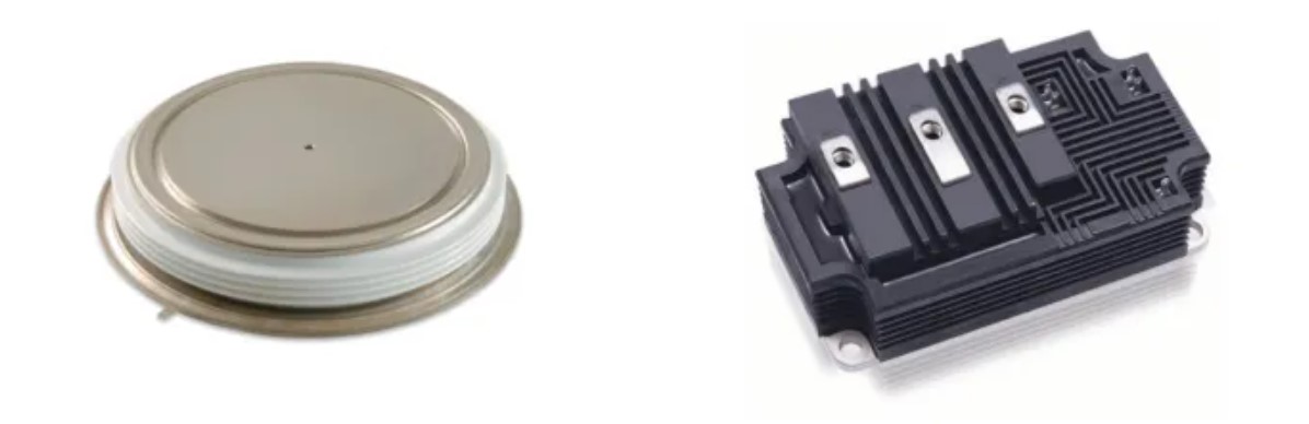
An IGCT is the thyristor equivalent of an IGBT. Since they are a type of thyristor, IGCTs are delivered in press pack packages. That contrasts with IGBTs which are available for a wider range of applications and are offered in a wider range of package styles (Figure 3). An IGCT is a combination of a GTO with an integrated gate structure. It delivers the high power density and low conduction losses of a GTO with a simplified gate drive.
An IGCT integrates the gate drive structure with a gate commutated thyristor (GCT) wafer-scale device. Both an IGCT and a GTO (from which the IGCT is derived) are controlled by a gate signal, and both can withstand high di/dt rates, meaning that no snubber is needed for most applications. In an IGCT, the gate current required to turn off the device is higher than the anode current. The high gate current combined with the high di/dt rates means that conventional interconnects can’t be used to connect the IGCT to the gate drive. Instead, the gate drive PCB and the IGCT are delivered as a single unit. The gate drive surrounds the device with a large circular conductor connecting to the edge of the IGCT. The large contact area and very short connection distance reduces the inductance and resistance of the gate connection, reducing the di/dt and supporting the efficient delivery of the high drive currents.
Like most thyristors, an IGCT is fabricated as a single wafer (Figure 4). That contrasts with an IGBT fabricated as a series of cells, with each cell constructed similarly to an n-channel vertical power MOSFET, except with a p+ collector layer replacing the n+ drain and forming a vertical PNP bipolar junction transistor.
 Figure 4: IGCTs are wafer-scale semiconductor devices with numerous integrated structures. (Source: Wikipedia)
The gate structure and drive topology for IGCTs support much faster turn-off times than GTOs. While GTOs are typically limited to operation at 500 Hz, an IGCT can operate at up to several kHz for a short period of time, with a long-term maximum switching frequency of 500 Hz. IGCTs are available with turn-off current ratings between 520 and 5,000 A and typical blocking voltage ratings of 4,500, 5,500, and 6,500 V. They are used in industrial and traction drives, variable-frequency inverters, and ac disconnect switches. Multiple IGCTs can be operated in series or parallel for higher power applications. While the schematic symbol for an IGBT is derived from the symbol for a MOSFET, the schematic symbol for an IGCT is derived from the symbol for a thyristor (Figure 5).

IGCTs are available with three structures:
- IGCTs capable of blocking reverse voltage are called symmetrical IGCTs, or S-IGCTs. The reverse blocking and forward blocking voltage ratings are usually the same.
- IGCTs incapable of blocking reverse voltage are called asymmetrical IGCTs, or A-IGCTs. They typically have a reverse breakdown rating in the tens of volts. A-IGCTs are used where a reverse voltage would never occur, such as in switching power supplies or DC traction drives. Or in combination with a parallel reverse conducting diode, such as in voltage source inverters.
- Asymmetrical IGCTs with a reverse conducting diode in the same package are called reverse conducting IGCTs, or RC-IGCTs.
IGBT vs. IGCT
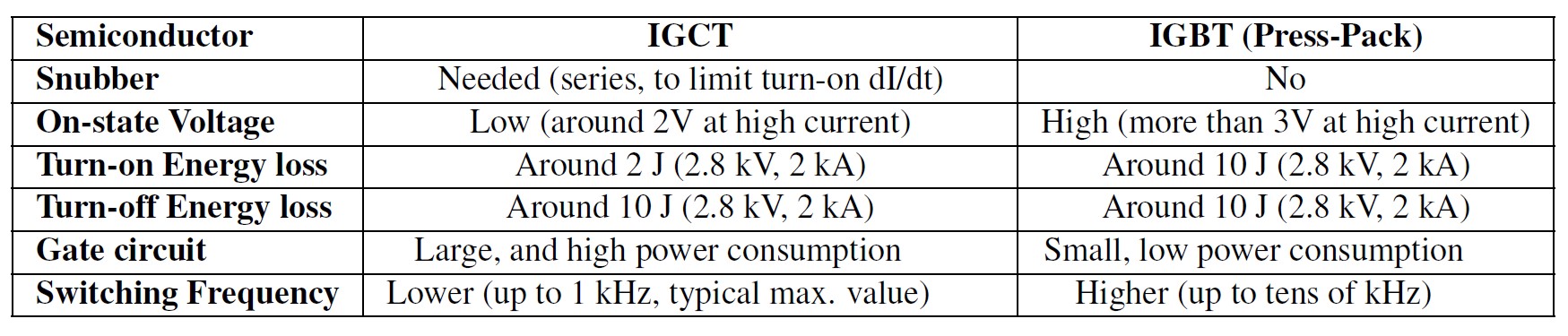
Because of their different operating principles, comparing IGBTs and IGCTs using datasheet ratings is difficult. In addition, IGBTs are available in a wider array of packages, resulting in a wider range of operating capabilities. By limiting the comparison to press pack devices, IGBTs and IGCTs can be compared using several factors such as the need for, or lack of need for, a snubber, their on-state voltages, turn-on and turn-off energy loss, gate circuit requirements, and switching frequencies (Table 1).
Summary
IGBTs and IGCTs are fully controllable four-layer power switches used in self-commutated power converters. IGBTs are derived from bipolar transistors, while IGCTs are based on gate turn off thyristors (GTOs). As a result, IGBTs can be used at lower voltages and lower power applications compared with IGCTs that are mostly used in applications that require operating voltages of at least 4,200 V and currents of over 500 A. IGCTs are slower switching devices, usually limited to about 500 Hz, while IGBTs can be operated at tens of kHz.
References
Applying IGCTs, ABB/Hitachi
Comparison of IGBT and IGCT, MB Drive Services
Figures-of-Merit and current metric for the comparison of IGCTs and IGBTs in Modular Multilevel Converters, EPE’20 ECCE Europe
IGBT: how does an Insulated Gate Bipolar Transistor work?, Infineon
IGCT Technology — A Quantum Leap for High-Power Converters, ABB
Insulated-gate bipolar transistor, Wikipedia
Integrated gate-commutated thyristor, Wikipedia

Leave a Reply