
by Kory Schroeder, Director of Product Marketing and Engineering, Stackpole Electronics Inc.
For high currents, axial-leaded wirewound resistors are often good candidates because they can handle up to 10 W and double as fuses.
When a task calls for dissipating kilowatts of power over an extended period, wirewound resistors are often a logical choice. These resistors are known for their ability to take high amounts of current. Wirewound resistors feature several parameters that are adjustable. This gives them advantages over film resistors.
Resistor manufacturers can tailor wirewounds to specific design requirements and to optimize their performance. Design engineers should understand what resistor attributes are adjustable and how adjustments can affect the performance of the device and the system.
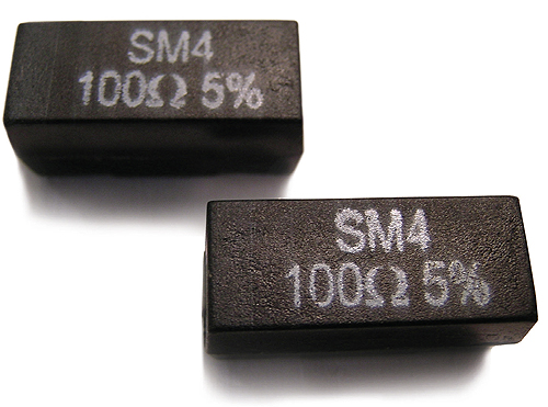
Wirewound resistors are inherently inductive because they are manufactured in the exact same way as wirewound inductors. The amount of inductance can vary widely from size to size and from value to value, but typically ranges from around 10 nH to 10 μH. Designers frequently request wirewound resistors made with lower inductance or that are wound non-inductively. To get a wirewound with less inductance, resistor manufacturers typically use a smaller wire size, which has a higher resistivity. Smaller wire delivers the desired resistance value with fewer turns. One side effect of this practice is a reduced ability to handle a power pulse because the wire mass has a lower resistance.
An Ayrton Perry winding method can create a non-inductively wound resistance. Ayrton Perry winding uses two elements wound in opposite directions on a single part, with both elements being essentially double the requested resistance value. The winding technique helps cancel the magnetic fields and lowers the inductance to between 0.1 and 1 nH typically. However, though they are dubbed non-inductive, non-inductively wound resistors still have some inductance. In addition, the Ayrton Perry winding process requires two precision wind operations. So it has a dramatically higher manufacturing cost, around twice that of ordinary wire-wound parts.
The need to handle higher power, or pulse power, can force use of a wire with a larger diameter, which lowers the wire resistivity. This practice can dramatically boost the wire mass available to dissipate electrical energy. There are two potential side effects. First, resistor inductance rises because it takes more turns to get a given resistance value. Second, there may also be some concerns about handling high voltages. Sufficiently high voltages can cause arcing between windings. Thus, windings spaced closely together are more prone to arcing, especially when there is a void present in the coating or molding.
There are two ways of designing wirewounds to withstand high voltage. The easiest and least expensive is to reduce the wire size, raising the resistivity of the wire element. This allows winding fewer turns, creating wider spacing between windings. The wide spacing minimizes the risk of internal arcing whether or not there is a void in the coating or molding around the part. This process also lowers the inductance of the part. As a result, the resistor would be able to handle less overall pulse power or pulse energy. These factors may or may not be relevant to a specific design. But it is important that designers understand the trade-offs associated with the ability to handle high voltages.
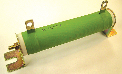
Simply reducing the wire diameter will not work for applications characterized by both high voltage and high pulse energy. These applications require element wire that is coated. The coating protects the resistor from arcing even if the windings touch each other. However, coated wire is much more difficult to weld and has higher manufacturing costs, so it is only used when absolutely necessary.
Of course, one potential drawback of any power circuit device is the possibility of overheating and potentially catching fire under the influence of a sufficiently high overload. Resistor manufacturers, such as Stackpole Electronics, can build wirewounds with a reliable and repeatable fusing characteristic.
One way of obtaining a fusing action is to use coating materials that concentrate the thermal energy so it doesn’t dissipate into the ambient air. Then with an overload, the part fuses quickly and typically with low thermal stress to the PCB and surrounding components. This method does not reduce the part’s ability to withstand short-term pulses. Another method of creating a fuse action is to reduce the wire size. The advantage to this method is that the resulting resistor is still straightforward to manufacture and less expensive than the first option. One limitation is that the component will be less able to handle short-term pulses.
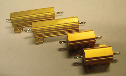
Because of the continued demand for smaller and lighter electronics, it’s now possible to get single-layer varistors and molded wirewounds in surface-mount packages. Surface-mount varistors use what is essentially a 5- or 7-mm single layer of semiconductor material pressed into a disk. The current and energy handling range for this type of device is somewhat limited.
However molded wirewounds in surface-mount packages can now be found with power ratings of up to 5 W. Though there is a price premium for these devices, they are comparatively small, light and reliable. Single-layer varistors in surface-mount packages have become more widely used, particularly with the development of surface-mounted wirewounds rated higher than 3 W.
All in all, wirewound resistors used in series with varistors are far more reliable than any film resistor because they are more robust and require significantly more energy to fuse. Moreover, the resistance of metal-electrode, leadless-face resistors and surface-mounted, pulse-withstanding chips will both begin to shift with prolonged exposure to surges. Eventually the devices will fuse. When this happens, the protection scheme is effectively gone and the protected circuit is exposed.
Stackpole Electronics
www.seielect.com

Leave a Reply