
 Phase shift full-bridge SMPS is massively over-hyped? – The Phase Shift Full Bridge (PSFB) converter is a hoax. The LTspice simulation (Editor’s note: see post for file) of a “plain” full-bridge SMPS bears this out. PSFB claims to be able to reduce switching losses compared to the “plain” full-bridge SMPS. However, the PSFB does have turn-OFF switching losses, just as does the “plain” full-bridge SMPS…so “no cigar” there for the PSFB. The PSFB does have zero turn-ON switching losses, but the “plain” full-bridge SMPS has very minimal switching losses anyway.
The only turn-ON switching loss of a “plain” full-bridge SMPS is that associated with the 1/2CV^2 loss due to the discharge of the FET’s Drain-source capacitance at turn-ON. But this is a small switching loss. The “plain” full-bridge SMPS has no “overlap” of FET voltage and current at turn-ON because the leakage inductance of the full-bridge transformer prevents the current from rising up quickly enough to do that. The downer for the PSFB is the large amount of circulating current in the primary of the PSFB transformer, this causes more conduction losses than the “plain” full-bridgeSMPS…so definitely “no cigar” for the PSFB here. The PSFB is simply a waste of time, its advantages are too insignificant to make it worth the extra expense. PSFB’s don’t even manage to get zero turn-ON switching losses when lightly loaded. Waste of money…do you agree? Read more
Current sense transformers on ETD type bobbins? – Would you agree that it is too risky to get SMPS current sense transformers wound onto ETD type bobbins? After all, if the winders forget to actually cross the primary wire back over itself then the primary may have zero coupling with the secondary, as the image below shows. As you know, this can’t happen with toroid cores since the winding is taken through the centre of the toroid, and therefore, there is always a completed turn of primary coupling up with the secondary. So do you agree that its best not to wind current sense transformers on ETD type bobbins? Read more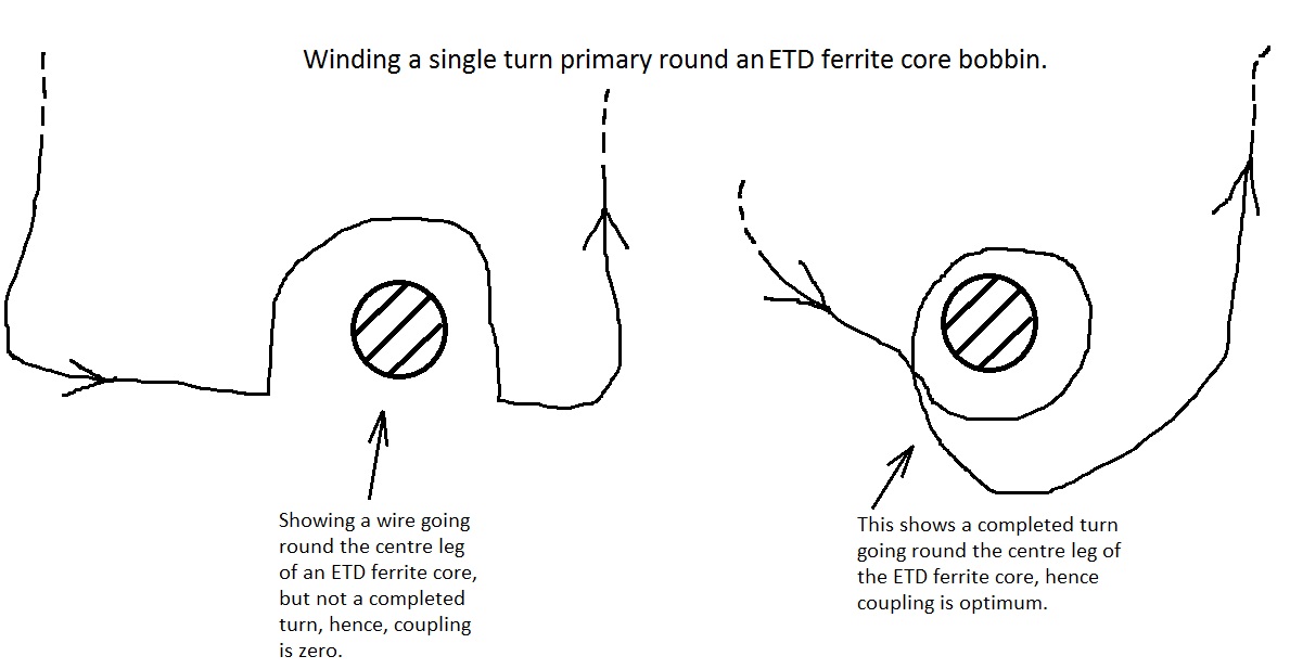
LM7912 regulator output is setting down to zero – LM7912 regulator output is setting down to zero after the current is drawn by the load. My project is the sensor from the field will give 8 to 48 mA outputwhich is read by the ADC. After that, it will be taken to the microcontroller, it will be sent to DAC, and the output of the DAC is 4 -20 mA. Whenever the unit is switched on for some time, the output of the DAC is going 45mA which is out of our scaling. There is no linearity between input mAmps and output mAmps. Whenever the output of DAC is 45mA , the output of the 7912 regulator is 0V. Please let me know if this is because of regulator or some other component. Read more
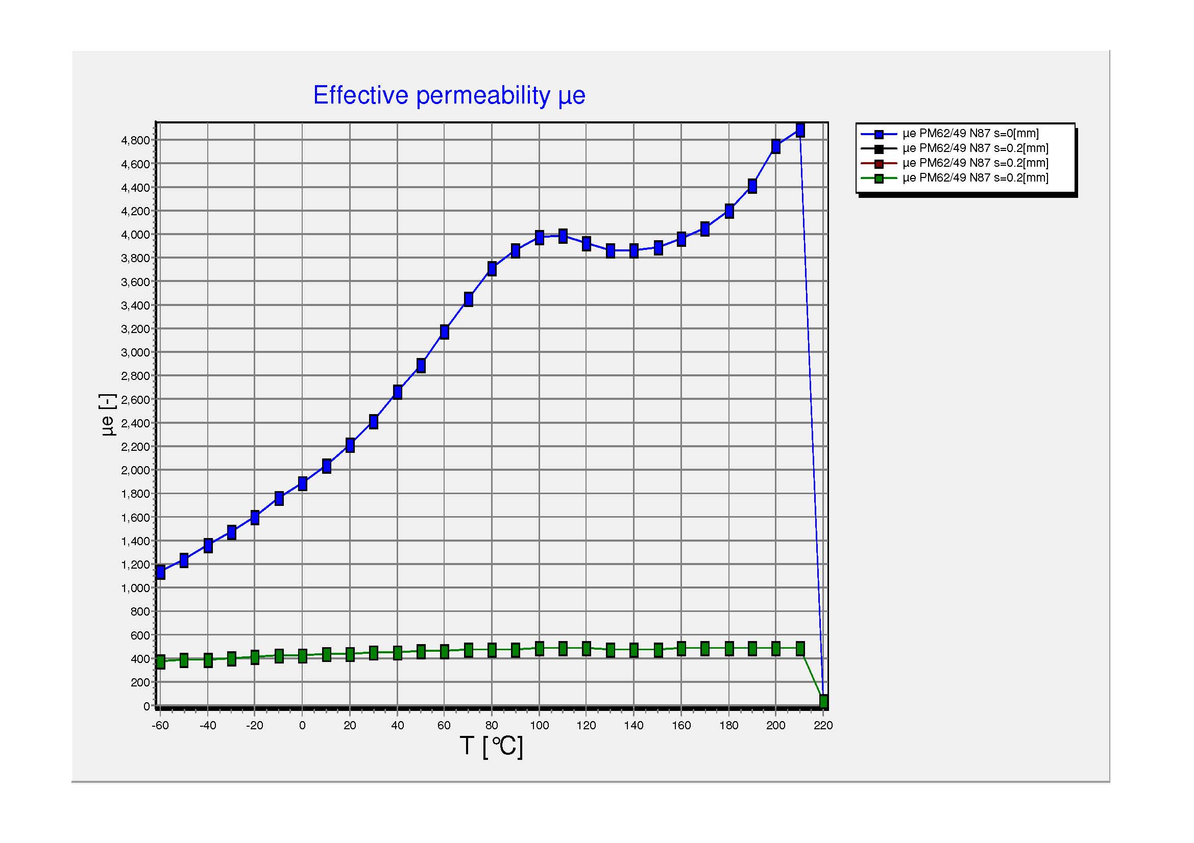
Gapping a ferrite core for full bridge SMPS transformer? – We are designing a 1.7kW Full Bridge SMPS transformer using a PM62/49 core by Epcos TDK (N87 material). We don’t want a gap in the core, but I believe we will have to have one because otherwise the change in the “saturation current” level {I(SAT)} varies too much as temperature changes. We need to know exactly what is our saturation current, and we simply cannot tolerate this level of variation in the saturation current level. If we work to the lowest level of saturation current, then we would in any case end up with a too big a core, as we would need to increase the core size. Therefore, we will add a gap to the centre leg of the core…(just 0.2mm)….this means that the ue value will not vary over temperature, as is seen in Epcos graph below. Do you agree we need the gap? Read more
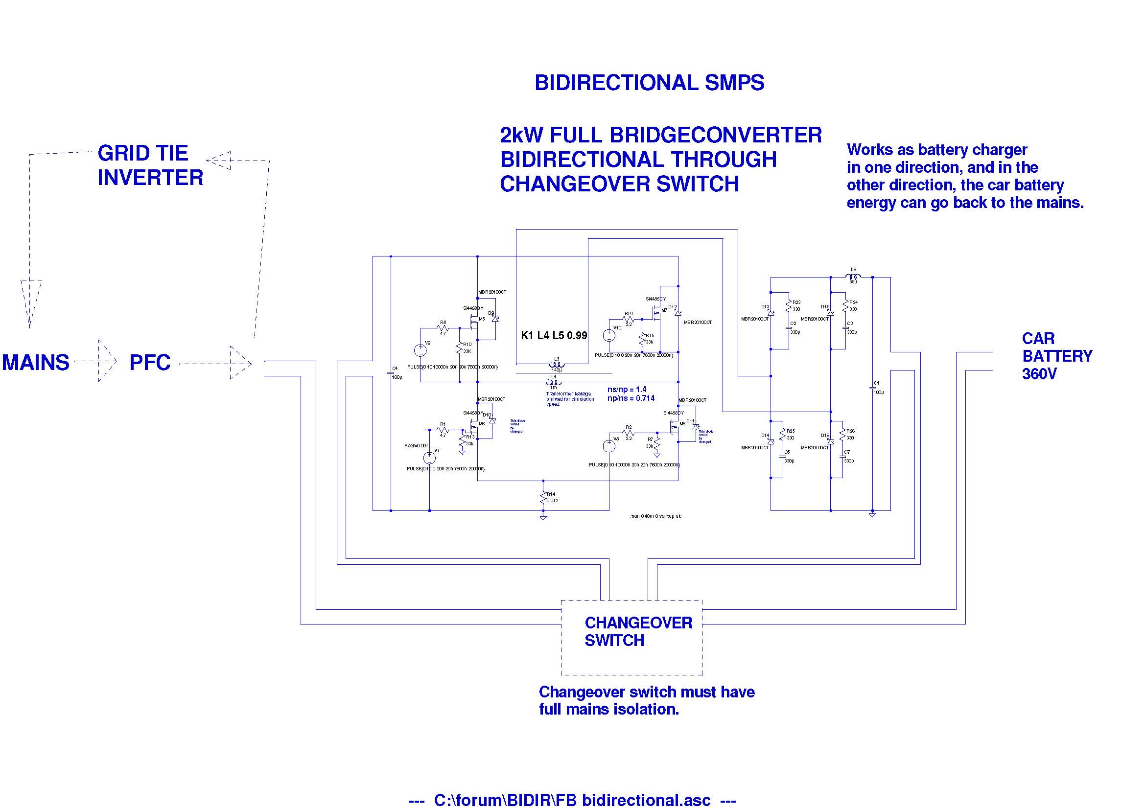
Is this the only way to get bidirectional, isolated SMPS with step-up and down? – We need to do a (small as possible) 2kW SMPS car battery charger which is bi-directional so that it can also put the battery energy back into the mains. Do you think the attached is a way to do it? If so, can you state if the needed “changeover switch” exists anywhere? Preferably the changeover switch could be electronically controlled, and could switch between circuits whilst preserving their mains isolation from each other. Read more
MOSFET ringing at switch ON step – When I switch the IRFP640 N Mosfet ON, I get some ringing. My guess is that this is due to the Miller effect. How can I avoid it? Read more
Half bridge LLCs vs full-bridge LLC converter? – Supposing that one has a wide output voltage range, then is it better to use a full-bridge LLC converter than a half-bridge LLC converter? I say this because the Q is lower for a given load when a full bridge LLC is used. And that surely means that the full bridge LLC can manage a wider output voltage range? Our spec is…
vin = 390VDC
Vout = 250 – 420VDC
Pout = 3kW
Read more
LF transformer as a PFC inductor – I need a quick set-up for a battery charger. I’m going to use a gas generator, a welder transformer, and a bridge rectifier. I’ve used it before but it was a real pain for the gas generator (not using any PFC circuit at all). I’ve read somewhere about using a(nother) regular LF transformer as a passive PFC inductor. They put the primary winding of the “PFC” transformer in series with the secondary winding of the main transformer (after bridge rectifier). And here comes the twilight part: If I remember correctly, the secondary winding of the “PFC” transformer has been shunted. Is that correct? Or should I left it open circuit? Read more
Triac PCB trace width & current – I’m creating a PCB for a digital switch circuit using Triac as a solid state relay.

The circuit is using BTA24-600B Triac and MOC3021 Optocoupler. The circuit will drive high loads as the Triac can drive up to 24 Amp current. I’m on the PCB design phase I need some expert person to help me on the following please:
- I have used online Trace calculators to know the suitable trace width that can carry 24 amperes. I need to know does this current will pass only through the Triac Terminals 1 and 2 to the load? i.e. the red wires in the above drawing only? Should any other black wire carry high current other than the red ones? I have read the datasheet for the Triac but couldn’t understand this info.
- Is there any distance requirement between high current traces on PCB? I have seen trace width calculators but do not know is there any minimum trace spacing requirement?
Leave a Reply