
Issues with TPS2811 MOSFET driver for IR530 in buck SMPS design – I’m trying to build an SMPS but want to simulate it on Multisim first before I buy all the components. The buck has a 6.3V dc input and will have a 5V dc output at 2 amps. I’ve designed a buck converter and it seems to work when I supply 12V dc with 400kHZ at 83% duty cycle into the gate of the mosfet. I’m trying to get my design with a gate driver but it doesn’t seem to work. I put VCC at 12 and put 5V dc at the input (I’m planning on using a microcontroller). For some reason it’s not working! I don’t have to use a microcontroller but would need some circuitry. Read more

Attempt to get my head around the correct magnetizing inductance – I’m trying to get a final idea in my head about what to do with designs and their magnetizing inductance. I have worked out what turns ratio I need, the minimum amount of primary turns needed with the core size, and desired saturation limit. I’ve also worked out the primary inductance given that amount of turns. Will more turn cause too high of inductance and cause spikes on the MOSFETs? Where do you draw the line and say well it needs to be this? Read more
Why is this opto-isolated feedback loop improvement method not more common in SMPS? – Page 16 of this eval board user manual shows a cascoded feedback loop optocoupler fed by a current source, this vastly improves SMPS transient response, and makes feedback loop compensation easier. Why is the technique not more used in offline, isolated SMPSs? Read more
MOSFET bridge giving power loss even with zero load – My MOSFET inverter (H-Bridge) is giving power loss of 4W even without a load. The gate input to all the MOSFETS are absolutely clean with almost no overshoot The gate voltage is 10V.

The details are :
V = 12V
F = 100KHz
MOSFET Rds = 1mOhm
Some where or the other both voltage and current are occurring simultaneously. But why? Where is this current pulse arising from? Read more
Magnetizing current in transformer – I am currently looking at a transformer design and I am a bit unsure on what is optimum for the design , the waveform on the transformer will be a short pulse of square waves ranging from 2KHz to 20Khz, maximum pulse length 50ms every 15% rep rate. I am unsure what the magnetizing current would be given this pulse waveform, whether the pulse waveform and rep rate effect this? Also, how do you determine when lowering the magnetizing current becomes non beneficial and you start losing more through copper losses etc? Read more
DC bus voltage to pure sinewave conversion ratio – If the DC bus voltage is 200v. PWM frequency 20KHz, Duty Cylce 10-90%, what is the maximum level of sinewave voltage which can be generated after filtering the output voltage? And, how is the sine table generated? Read more
Current sensing in pushpull topology – I’m building a 12-440V/500W push-pull converter based on the UC2825A PWM controller. The current sense xfrm (toroid) is now placed over the common junction of the two primaries, thus receiving unipolar pulses. The max duty cycle is ~93% so it has very short time to reset and fails to do so at heavy loads–the sensed current assumes negative slope. If I slide on a bigger core it works, but the reset pulses wildly exceed -500V. Even though they are about 300ns each, I don’t feel comfortable running them close to other sensitive lines. Read more
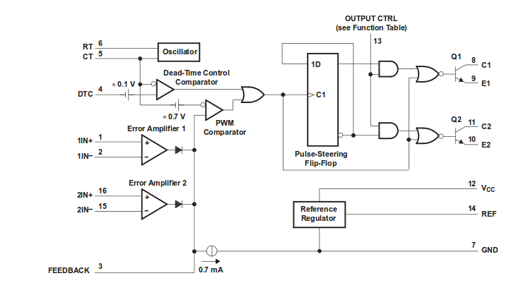
PWM generation using TL494 – I need to generate a fixed frequency and variable duty cycle PWM signal. Normally I would’ve used a microcontroller, but due to unavoidable circumstances, I have to use the TL494. I did an extensive study of the datasheet, but there are some doubts which I need to be cleared. Read more
Why is this high-side FET drive method for SMPS never mentioned? – This article on MOSFET gate drive methods is amongst the world’s finest. Why then, does Balogh not mention the method of using an external gate drive supply SMPS? As you know, this method means having isolated outputs which simply feed a gate drive IC next to the high side FET. A digital isolator couples the gate drive signal to the high side gate driver. Read more
Buck converter does not step up current but steps down voltage – I am designing a buck converter to step down 24 volts to 12 volts to charge a battery. So far, I am successful in stepping down the voltage but the main issue which I am facing is that the input current is higher than the output current which should be the other way around. I am using the IR 2112 as the gate driver. Read more
Leave a Reply