
by Rakesh Raja and Sudhir Nagaraj || Closed-loop current regulation in stepper motors plays a major role in determining the accuracy and smoothness of motor motion. The scheme of current control also determines the power efficiency of the motor drive system. A typical pulse-width modulation (PWM) control loop used today has a suite of fixed-decay schemes such as slow, fast and mixed decay to handle the re-circulation (decay) current.
Closed-loop current regulation in stepper motors plays a major role in determining the accuracy and smoothness of motor motion. The scheme of current control also determines the power efficiency of the motor drive system. A typical pulse-width modulation (PWM) control loop used today has a suite of fixed-decay schemes such as slow, fast and mixed decay to handle the re-circulation (decay) current.
Finding a decay scheme that works for a stepper motor system is time-consuming and involves trade-offs. The right setting depends on various factors such as supply voltage, current being regulated, motor characteristics, motor speed and back electromotive force (back-EMF). The fixed-decay scheme selected can become sub-optimal over time as battery supply voltage and motor characteristics change, and so on, as does not handle back-EMF well. This article introduces an intelligent decay scheme that minimizes ripple, responds quickly to step changes, adapts to changes in supply, load and back-EMF. This plug-and-play scheme eliminates any need for tuning the motor.
Current regulation
An H-bridge comprising four MOSFETs are used to drive motor winding. The motor is turned on by switching on FETs such that a voltage is applied across the motor winding. The motor current is controlled precisely to get good position control of the motor. Figure 1 shows the current profile through a stepper motor with two coils. Current through the two coils is controlled to generate sinusoidal profiles that are 90 degrees out-of-phase with each other.
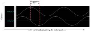
Each step is associated with a certain amount of current through each coil and results in a particular position of the motor. With each step, the current profile advances to the next level, making the motor move to the next step.
Common-current regulation schemes
The method used to regulate current is called decaying the current or recirculation of current. One decay scheme reverses the polarity of voltage applied across the motor. This scheme, called fast decay, results in a decay rate that is the same as the charge rate. Another scheme turns on low-side field-effect transistor (FETs) allowing current to recirculate through them. This scheme is called slow decay and results in a slower current decay than fast decay. A third option is called mixed-decay, which performs fast decay initially, followed by slow decay.
Why are decay schemes important?
The optimal decay scheme depends on various factors like supply voltage, motor resistance and inductance, motor rotation speed, and back-EMF. Listed are some of the trade-offs and limitations with the aforementioned fixed-decay schemes.
- At small current levels, slow decay can result in loss of regulation due to the inability to discharge current built up during the minimum on time. In this case, fast decay is preferred. However, regulating larger currents with fast decay results in larger ripple than does slow decay.
- Fast decay provides faster step response, but it is at the expense of undershoot and larger ripple once holding-current is reached.
- A fast-decay setting has poor power efficiency due to switching losses.
- Fast decay cannot handle back-EMF well.
- Time-consuming manual tuning is needed for each system to find a decay setting that is acceptable. Re-tuning is necessary when any parameter changes in the system (new motor, changing motor speed, motor aging, supply voltage change, and so on). Customers typically spend weeks to months tuning a motor to find an acceptable setting.
Introducing AutoTune
AutoTune™ is an automatic plug-and-play scheme that detects the optimal decay setting on-the-fly. It dynamically adjusts the decay setting to adapt to system changes. The block diagram in Figure 2 shows how the AutoTune controller interacts with the H-bridge motor driver.
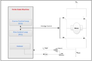
AutoTune deploys a mechanism called decay-locked loop (DLL), which is similar to the well-known phase-locked loop (PLL). Just like the PLL using a feedback mechanism to lock to a specific clock frequency, DLL uses feedback from the H-bridge to lock on to a specific drive time for the motor within a PWM cycle. Since this scheme uses a fixed off time, once on-time lock is achieved, subsequent PWM cycles look very similar. This helps avoid sub-harmonic oscillations and keep the PWM switching activity above an audio frequency range. This ensures a significantly smoother and quieter motor operation.
DLL dynamically adjusts the fast-decay duration (TFAST) of the total decay time cycle-by-cycle to converge on the fixed on time. For this, DLL uses two feedback control loops: coarse control loop (CCL), and fine control loop (FCL) (Figure 2). The basic feedback mechanism depends on the duration of drive time it takes for the current to reach the regulation current level (I_TRIP). Figure 3 shows each PWM cycle and the timing parameters used by the algorithm.
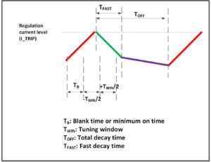
A timing window (TWIN) is defined right after the minimum motor on time (TB). The goal is to converge on a drive time of (TB + TWIN/2). If I_TRIP happens outside TWIN, CCL increases or decreases TFAST in big coarse steps until I_TRIP occurs within TWIN. Once I_TRIP occurs within TWIN, FCL kicks in to make fine adjustments to TFAST.
Figure 4 shows an example waveform where I_TRIP happens before TWIN resulting in TFAST increasing from 1 TB to (15 percent TOFF) to (30 percent TOFF). After that, the algorithm achieves lock and makes fine adjustments to secure precise control of the I_TRIP location.
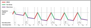
Figure 5 shows another example waveform where I_TRIP happens after TWIN, resulting in TFAST decreasing from (60 percent TOFF) to (30 percent TOFF) to (15 percent TOFF). Fine adjustments are then made by FCL.
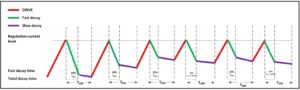
Another important aspect of the dynamic scheme is how it handles STEP commands that result in decreasing current. To quickly get to the new regulation level, the algorithm quickly increases TFAST and, if needed, switches to 100 percent fast decay. Figure 6 shows an example of such a case. Once regulation level is achieved, the previously described DLL with CCL/FCL takes control.

Benefits of AutoTune
Some of the benefits of such a plug-and-play scheme are:
- Development cost: No need to spend weeks to months tuning the motor!
- Efficiency: Motor runs more efficiently than fixed decay modes. This is achieved by maximizing the slow decay as much as possible and keeping fast decay to a minimum. Slow decay is more efficient than fast decay. Hence better efficiency is attained.
- Production risk management: Makes it easier to manage supply chain motors. Customers can change motor vendors at any time and do not have to re-tune.
- Reliability: The scheme adjusts to changing system parameters like motor resistance (goes up with age), supply voltage droop (which is especially important for battery-powered applications), motor speed profile changes, and other instances These features result in overall higher system reliability over the lifetime of the motor
- Performance: Motor operation is quieter because sub-harmonics in the audio band are eliminated.
- Ripple: Due to maximizing slow decay, ripple is reduced significantly when compared to fixed-decay schemes.
- Settling time: Faster response to step commands result in precise control of the motor current profile.
- Back-EMF Control: Better control of back-EMF as AutoTune dynamically adapts to system changes.
Summary
Most stepper motor systems use fixed-decay schemes such as slow, fast or mixed decay. A new generation of stepper driver integrated circuits (ICs), such as the Texas Instruments’ DRV8880, incorporate plug-and-play decay schemes like AutoTune that provide significant benefits to the motor design community. With AutoTune, spending weeks to months tuning a motor may soon become a thing of the past.
About the authors
As a digital design manager of TI’s motor drive design team, Rakesh Raja is responsible for the design of motor drive ICs. Rakesh is a Member, Group Technical Staff (MGTS) of TI’s Technical Ladder, and has a Masters in Electrical Engineering Degree from University of Texas, Dallas.
Sudhir Nagaraj is an analog design manager of TI’s motor drive design team. Sudhir is involved with designing high-voltage motor drive and magnetic sensing ICs, and he has a Masters degree in Electrical Engineering from Columbia University.
Leave a Reply