Modern battery, fuel cell and solar cell systems need ways of transferring power in two directions. New dc-dc converters that are bidirectional can eliminate the need for bulky transformers in these applications while bringing more efficient operation.
ANKUR PATEL
VICOR CORP.

 ALTERNATIVE energy scenarios involving renewable sources are characterized by the sending of power both up and down utility lines. This bidirectional mode of energy handling has fostered interest in efficient power converters able to handle energy flows equally well in both directions.
In that regard, a new zero-voltage switching (ZVS) bidirectional dc-dc converter (BDC) module has been developed to exhibit higher efficiency and power density, greater reliability and isolation than existing BDCs. At power levels up to 1.65 kW, the 384-to-48-V BDC provides efficiency boosts of 13.5%, 3.4% and 1.5% at loads of 10%, 50% and 100%, respectively. As a result, the new BDC is a promising choice for fuel cell, solar cell and battery applications. It is also a high-energy density option for hybrid and electric vehicles, UPS, telecom, and power grid applications characterized by a need for high efficiency at both light and at full loads.

Most existing ZVS bidirectional and unidirectional dc-dc converters are low-power devices that can be paralleled to handle high power. Methods to handle the power conversion inefficiencies of such arrangements at light-load or no-load operation fail to deal with the fast and frequent changes in power inputs encountered in renewable power generation, which vary with wind speed and solar intensity. The new BDC will also reduce the number of power conversion steps required in most designs and eliminate the heavy, bulky 50 to 60-Hz power transformer needed to isolate current systems from the ac power grid.
INSIDE A BDC
This new BDC is a fixed-ratio dc-dc converter. (DC-DC converters without output regulation are termed “fixed ratio” because the output voltage is a fixed ratio of the input voltage.) It supports a wide range of input currents and voltages. Its topology is that of a Sine Amplitude Converter (SAC).
Though it has been in use for years, SAC topology may be unfamiliar to some engineers. As a brief review of its operating principles, first consider ordinary dc-dc converters that drive a power inductor or transformer with a square wave. The switch elements (usually MOSFETs) dissipate power during switching, and the square wave is rich with harmonics that must be filtered out.

The output power in this converter is proportional to the converter duty cycle which is controlled via pulse-width modulation to provide more or less power from the transformer secondary. The basic PWM converters can be improved with ZVS and ZCS (zero current switching) by adding a capacitor in the primary circuit to form a quasi-resonant circuit, and by switching the switch elements at the zero-voltage and zero-current crossings.
In conventional PWM ZCS/ZVS schemes, energy in the transformer primary is proportional to 1/2LI2 where L is the primary inductance and I is primary current. Energy transfer is constant for a given circuit configuration. To increase the rate at which energy transfers to the transformer secondary, the switching rate must rise. Thus output power depends directly on switching frequency. Switching frequencies in ZCS/ZVS resonant converter have a trade-off between stored energy per cycle and the conditions needed to realize ZVS/ZCS.
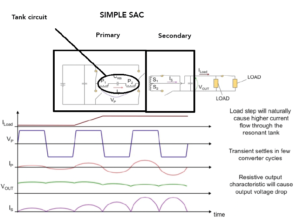
SAC topology resembles that of ZCS/ZVS but works differently. SACs operate at a fixed frequency equal to the resonant frequency of the primary side tank circuit — there is no PWM. The frequency is fixed regardless of load on the secondary.
When the load increases, the SAC reacts by boosting the amplitude of the sinusoidal current on the primary resonant tank, increasing the energy coupled into the secondary. The FETs in the SAC primary circuit switch at zero-crossing points, and the current in the primary resonant tank is a pure sinusoid, greatly reducing harmonic content. Unlike ordinary ZCS/ZVS circuits, the transformer leakage inductance in SAC is not a critical energy storage element. So the SAC can operate at much higher frequencies, allowing the use of a small transformer.
To understand how an SAC operates, it is useful to describe its primary circuit in more detail. The SAC creates a low-voltage sinusoidal oscillation by resonating the small amount of leakage inductance present in the power transformer with a primary-side capacitor. The amplitude of this oscillation varies with the current drawn by the load. As the load current rises, the amplitude of the oscillation (as measured across the resonant capacitor) also rises. When the load draws no current, the amplitude drops to zero.
The SAC topology is also useful because it is inherently bidirectional. The SAC topology incorporates synchronous rectification on the secondary side of the transformer, so the converter can process power “backwards,” from the output back to the input. In other words, it can both source current to the load and sink current away from the load. As a result, whenever the output voltage exceeds the input voltage multiplied by the transformer turns ratio, power will flow from the output to the input. Reverse power flow is efficient: Energy taken from the output is delivered to the SAC input, except for incidental losses, such as the loss in parasitic circuit resistances.
ANALYZING OPERATIONS
In the case of the BCS, the primary circuit is a half-bridge that is stacked (high side and low side devices mounted on opposite sides of a common conductive interface). The primary also uses low-voltage MOSFETs to reduce conduction losses and to realize low switching losses across the entire load range because of ZVS/ZCS technology. The secondary circuit is center-tapped with synchronous rectification. A high-frequency transformer provides galvanic isolation. In ideal conditions, its voltage and current ratios are defined by the following equation, with K being the transformer’s turns ratio.

The BDC employs a 1.1 MHz switching frequency. The input capacitors (CIN) are specified to be identical so they balance the voltage in the stacked half-bridge primary circuit, which facilitates storing the same energy in each primary winding. The output voltage is proportional to the input voltage minus the voltage drop due to the combined resistance of the MOSFET’s RDS-ON , the PCB trace and transformer’s winding resistance.
The new BDC uses a planar transformer for low losses and galvanic isolation. The bidirectional BDC provides step-down dc-dc conversion when operating from input-to-output terminals – forward mode. It’s implemented by connecting a high-voltage source to the input terminals and a low-voltage load to the output terminals.
To enable backward mode, the BDC first must be turned on in forward mode, because SAC control is on the input side. This turn-on takes place by applying a low voltage to the input terminals. Then, when the voltage applied to output terminals exceeds the turns ratio times the input voltage, the BDC enters backward mode, providing step-up, low-voltage-to-high-voltage dc-dc conversion from the output terminals to the input terminals.
A start-up circuit based on flyback topology, receiving its input from the low-voltage side, may be used to enable backward power flow. Then, the high voltage side provides the bias voltage and current to SAC control. The low line of the BDC on the high voltage side is 260 V. There is an under-voltage turn-on point below the low line where the BDC turns on.


 The new BDC, with a transformation factor (K) of 1/8, is used to implement 384-to-48-V bidirectional conversions. Two PCB prototypes have been designed implementing the BDCs. The input voltage is 384 V in the forward direction and 48 V in backward mode. The load current ranges are 0-to-35 A and 0-to-4.5 A in forward and backward directions, respectively.
In one case where the new BDC is used, a dc micro-grid has a 384-V high-voltage dc (HVDC) side and low-voltage dc (LVDC) side at 48 V, 24 V and 12 V. The external 230-Vac grid is rectified and converted to 384 Vdc for the HVDC bus by one centralized PFC boost rectifier. The BDCs will convert HVDC to the lower dc voltages. The centralization improves efficiency by eliminating redundant conversions.
A BOON FOR ALTERNATIVE ENERGY
The new BDC can interface the low-voltage generated by solar cells to the HVDC bus. The bidirectional PFC boost rectifier can shift excess power generated by the home back to the power grid. Excess power can also be stored locally by using the proposed BDC to lower the HVDC to storage system levels. Similarly, the high efficiency, compact size, light weight and high reliability of the new BDC are vital for hybrid vehicles.
The same can be said for ac/dc grid systems. The BDC eliminates the need for a heavy, bulky 50 to 60 Hz power transformer by effecting galvanic isolation and voltage matching at 1.1 MHz. For bidirectional power processing in energy storage systems, the proposed BDC would provide current from a 380-V bus to charge a battery bank in the forward direction or to provide energy from the battery bank backward to the high-voltage bus. In one case, two post regulator modules (PRMs) regulating against line and load and are implemented using Vicor ZVS buck-boost regulator modules.
REFERENCES
VI Chip BCM Bus Converter Module Data Sheet, Rev1.9, 04/2011
Maxi dc-dc Converter Data Sheet Rev9.2, 09/2014
Chip BCM Bus Converter Module Data Sheet Rev1.3, 05/2015
VIA BCM High Voltage Bus Converter Module Data Sheet Rev1.1 06/2015
“Vicor Factorized Power Architecture and VI Chips,” Vicor White Paper
Webb, Victor-Juan, “Design of a 380 V/24 VDC micro-grid for residential DC distribution” (2013). Theses and Dissertations. Paper 231.
Sonya Gargies, Hongjie Wu and Chris Mi, “Isolated Bidirectional dc-dc Converter for Hybrid Electric Vehicle Application” (2006)
Fan Haifeng, “Advanced Medium-Voltage Bidirectional dc-dc Conversion Systems for Future Electric Energy Delivery and Management Systems” (2011) Electronic Theses, Treatises and Dissertations. Page 4507.
Hamid R. Karshenas, Hamid Daneshpajooh, Alireza Safaee, Praveen Jain and Alireza Bakhshai, “Bidirectional dc-dc Converters for Energy Storage Systems, Energy Storage in the Emerging Era of Smart Grids“, Prof. Rosario Carbone (Ed.), ISBN: 978-953-307-269-2, InTech
Xiaoyan Yu and Paul Yeaman, “A new high efficiency isolated bi-directional dc-dc converter for DC-bus and battery bank interface,” in 2014 Applied Power Electronics Conference
VI Chip PRM Pre Regulator Module Data Sheet, Rev1.2, 08/2013


Leave a Reply