The low voltage available from a single supercapacitor forces most applications to use several supercaps in series. Here are the tricks involved in stringing these components together.
Robert Chao | Advanced Linear Devices Inc.

The average supercapacitor has a maximum charging voltage of between 2.5 and 2.7 V. For many applications a voltage this low isn’t particularly useful, so the common practice is to place multiple supercapacitor in series. Unfortunately, supercapacitors may have a tolerance difference in capacitance, resistance and leakage current. These differences create an imbalance in the cell voltages of supercapacitor wired in series. It is important to keep the voltage on any single cell below its maximum recommended working voltage. Otherwise the supercapacitor could degrade from electrolyte decomposition, gas generation, or a rising effective series resistance (ESR).
The factor that initially dominates imbalance is the capacitance difference between cells — a cell with a lower capacitance will charge to a higher voltage in a series string. Supercapacitor capacitance values may differ as much as ±20% (total of 40%) from cell to cell. For example, in a batch of supercapacitors it is possible to find one cell rated at 2.7 V with a capacitance value of 100 F next to one at 127 F. If these two cells are wired together in a 5-V stack, one could settle at 2.2 V and the second could reach 2.8 V, which is out of spec.
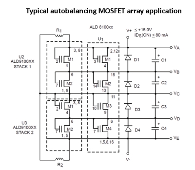
The usual way of dealing with these imbalances is to put a balancing circuit in parallel with the supercapacitor stack. One such technique places a bypass resistor in parallel with each cell, sized to swamp out the cell leakage current. When resistors with the same value are in parallel with all cells, the cells with higher voltages will discharge through the external resistor at a higher rate than the cells with lower voltages. This action helps distribute the total stack voltage evenly across the entire series of capacitors. Applications with a limited energy source or high level of cycling might use an active voltage balancing circuit instead of a resistor network. The active balancing circuit typically draws much less current in steady state and only requires larger currents when the cell voltage is out of balance.
But the problem with balancing circuits is that they are ineffective if there is too much variation among the cells. To avoid this, a designers should pre-measure and pair supercapacitor together with similar capacitance values. Given the example above, designer would group all cells together with a capacitance value between 100 and 110 F. Similarly, all cells between 120 and 130 F should be sorted and placed in the same supercapacitor stack.
After each cell is tested and matched, the next step is to test each supercapacitor for leakage current. Manufacturers often do not provide or guarantee leakage values, so designers must determine this parameter before placing a cell in a circuit for balancing. A standard method for gauging leakage current is to power up the supercapacitor with a small resistor such as 100 Ω at 2.7 V over 96 hrs. to measure a settled value. The initial current into the cell is the supercapacitor charging current. Once completely charged, any residual current detected determines the dc leakage current. Notice only a max leakage is mentioned, as a cell could have values that vary widely from those of other cells but can be balanced if leakage is below an allowed value.
Thus, there are four steps that will ensure cells in a series stack will balance.
1. Determine the individual capacitance value of each cell.
2. Group the supercapacitors with similar capacitance values together. To realize voltage levels that are within limits for each cell in the stack, the capacitance values of each cell must be reasonably close to that of other cells.
3. Once the cells are grouped by capacitance values, determine the leakage currents of each group.
4. Finally, group together cells that have similar capacitance and leakage current.
The next step is to choose a balancing method suitable for the currents involved. For example, if the leakage current spec is 23 µA, a SAB (supercapacitor auto balancing) MOSFET could be used to balance leakage currents up to 230 µA (up to ten times the nominal max leakage current value).

With the balancing method determined, it’s time to place two similar leakage-tested supercapacitors in series and power them up. For example, if the voltage rating is 2.7 V for each cell, then the two-cell stack may be operated at 5 V, which leaves a 0.2 V voltage margin. A more conservative operating voltage range may be 4.2 to 4.6 V instead of 5 V.
The balancing method should result in little or no change in the voltage over time. A SAB MOSFET, for example, will balance the supercapacitor by preventing leakage current imbalance from causing an excessive voltage to change in either cell so that it protects the supercapacitor from drifting into a dangerous state.
It’s important to remember that the balancing of individual supercapacitor cells is a relatively new horizon, as is the use of series stacks. Engineers with relatively little experience in supercapacitor deployments are just now starting to cope with these nuances. When in doubt, allow extra voltage margins for all the possible lot-to-lot capacitance variations to ensure cells don’t see over-voltages.
All in all, engineers need to test cells individually to get a more accurate reading of individual capacitance and leakage current values. Only then can designers begin the process of grouping cells together within a certain range before the balancing begins. Once incorporated into the design process, it will help ensure durability and reliability for the life of the application.


Cool…..
The text above “For example, if the voltage rating is 2.7 V for each cell, then the two-cell stack may be operated at 5 V, which leaves a 0.2 V voltage margin” Is wrong. The operating voltage of each cap is 2.7V and caps in series gives a voltage headroom of 0.4v (0.2. volts per cap) since each cap would be charged to 2.5 volts.
Balancing boards(1 per cap) are usually used on caps in series and start to kick in around 2.5 volts and bypass the charge beyond 2.7 Volts per cap. This protects the cap from overvoltage.
Overvoltage charge reduces the devices life and leads to device failure quick.