It’s easy to over-specify a cooling fan. But there are ways of keeping temperature down with fans that are sized just right.
JEFF SMOOT | CUI INC.
THE FIRST STEP in any thermal management task is understanding the thermal path taken for removing excess heat. Most systems, and particularly those that employ an enclosure, will use some form of forced air cooling. Invariably the cooling will involve a fan of some kind. The choice of fan, particularly for an enclosed PCB can have a significant impact on the overall lifespan of a system.

Conduction is the simplest means to remove heat simply because heat spontaneously flows from a hotter to a colder body. However, an electronic assembly sitting in an enclosure such as a rack-mount will not be able to dissipate much heat through conduction. For this reason, assemblies that consume as little as 25 W of power may require forced-air cooling.
To grasp the scale of the cooling problem, engineers create what’s called a thermal profile. This is basically a record of how much heat a system generates, when it gets generated, and where the heat sources are. The approach to creating the profile starts with placing temperature sensors at various points on the PCB.
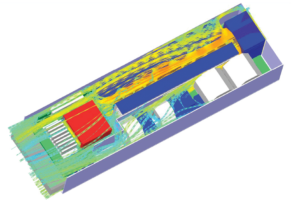
Also important for system profiling is how much impedance to airflow a system exhibits. The system impedance is expressed in terms of a drop in air pressure between inlet and outlet. It plays a major part in calculating the overall airflow required from a fan and, in turn, the selection of the size and type of fan. Designers can determine system impedance by measuring the pressure drop using sensors or, if possible, by placing the system in an air chamber. For larger systems –such as data centers – it may be possible to model the system using CFD (computational fluid dynamics) to get an even more accurate profile.
Forced air cooling plays a big role in thermal management, but the question becomes how much forced air is enough. To get the answer, it is necessary to figure out by how much the internal temperature can change without increasing the risk of failure.
The process begins with determining the ‘most critical’ component in terms of operating temperature; this component’s maximum temperature will give a maximum ambient temperature allowable. The total power dissipation for all relevant components — such as power transistors, microprocessors, amplifiers and communication interfaces — will provide a figure for the amount of power the overall design dissipates.
Power dissipated, in Watts, converts linearly to energy in Joules/second, which is in turn exhibited as heat. One can assume that the temperature of the air around the components will continue to rise while the equipment operates. At some point air temperature will reach a level that will inhibit the removal of additional heat. Thus he point of adding forced air is to replace the heated air with cooler ambient air. The air flow must be sufficient to accomplish this while keeping components below their maximum operating temperature.
Equation 1 shows the relationship between temperature rise and airflow, where q is the amount of heat absorbed by the air (W), w is the mass flow of air (kg/sec), Cp is the specific heat of air (J/kg°K) and ΔT is the temperature rise of the air (°C):
q = w × Cp × ΔT (1)
Once we know the maximum permissible temperature within the enclosure and we derive the amount of heat generated (based on the cumulative power/heat dissipated by the components) it is possible to calculate how much airflow we need. Because mass flow (w) = air flow (Q) × density (ρ), substituting and solving for Q we can rewrite Equation 1 to get Equation 2 (where Q is the airflow in CMM (m3/min), q is the amount of heat to be dissipated (W) and ρ is the density of air (kg/m3)).
![]() (2)
(2)
Substituting constants for Cp and ρ at 26°C, we can arrive at a general equation for calculating airflow, Equation 3.
 (3)
(3)
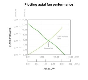
The calculated airflow figure can now be compared with the fan specification. Manufacturers characterize fans using these two parameters to provide a performance graph that plots airflow (measured in either CMM or in cubic feet per minute, CFM) against static pressure (measured in either inches or millimeters of water, often written as inch H2O or mm H2O).


Consider the performance curve of the CFM-120 Series from CUI, a 120×120-mm frame axial fan with dual ball bearing construction. Unfortunately, the result given by Equation 3 is only accurate for ‘ideal’ conditions; with no back pressure from the enclosure (known as system impedance). In reality, there will always be some system impedance. So to determine the real-world requirements engineers must calculate or estimate the system impedance. This impedance can then be plotted on the fan performance curve, and the point at which they cross should be taken as the operating point for the fan.
In many cases, it is not possible to measure the airflow through an enclosure using an airflow chamber. The alternative is to specify the operating point above the figure derived from Equation 3.
For example, if the airflow calculated is 50 CFM with zero back pressure, there will be a good margin of error with a fan over-specified such that it produces a maximum of 100 CFM with the intention of operating it at 75 CFM. The higher figure also provides some headroom for increasing airflow during operation.
Obviously, minimizing system impedance helps keep down the size of the necessary cooling fan. At a minimum, it is good practice to keep the areas around the air inlet and outlet as clear of components as possible. Also keep in mind that an air filter will add system impedance. Component placement on the PCB should encourage airflow to and around critical components, using guides if needed.
In addition, note that the above equations use air density at sea level. A system that will work at altitudes significantly above sea level must factor in the thinner air. A significantly higher altitude would need much more airflow to maintain the same level of cooling.
Choosing the right fan
Fans are generally categorized by the way the air enters and leaves. If it exits in the same plane as it enters then the fan is normally termed an axial fan, as to draw air in from one side and expel it from the other on the same axis. If the airflow leaves in a different plane the fan is normally referred to as a centrifugal design because the air drawn in changes direction inside the fan and is expelled in a different direction. This style of fan can effectively compress the air, allowing delivery of a constant airflow under different pressures. Perhaps the most prolific centrifugal fan design is the blower, which resembles an axial fan but typically expels air at 90° to the intake.
The volume of airflow needed and the static pressure of the system will influence what style of fan makes sense for a given application. Axial fans are predominantly suitable for high airflow in systems with low static pressure, while centrifugal fans offer lower airflow but can deliver it against higher static pressure.
Both audible and electrical noise are also important when selecting a fan. The general rule of thumb is that fans producing greater airflow will also generate more audible noise. Thus, axial fans will typically have lower audible noise than blowers. To keep down audible noise, designers must optimize airflow and reduce system impedance, thus reducing the required CFM.
Besides generating audible noise, dc fans can have other design considerations. The dc motor within the fan creates an electromagnetic interference (EMI) signature. These emissions are normally limited to conducted EMI in the power leads. Ferrite beads, shielding or filtering can all mitigate such effects. For most PCB-based systems in an enclosure, the dc axial fan provides the right balance among cost, audible noise, EMI, and performance.
Differences in the construction of axial fans may also impact how they are used. Generally, these differences relate to the bearings. Bearings on the fan shaft can be either steel ball bearings or sintered powdered bearings, usually referred to as sleeve bearings. At consistently low temperatures, fans with sleeve bearings can operate as well as ball bearing fans. However, at variable or high temperatures, ball bearings have been shown to operate longer and more reliably. Sleeve bearing fans, which are normally cheaper than ball bearing fans, do have their place. But their relatively short lifetime and propensity to fail at high temperatures limits their use.
Axial fans are widely used in rack-mount enclosures thanks to their combination of small size, low power dissipation, and high airflow. Many also include features that can boost system performance by controlling fan speed, optimizing a design to reduce power consumption. Design calculations of minimum required airflow rate help specify a fan that can cool under all conditions. They assume the fan runs constantly, even when maximum cooling is unnecessary. Thus the design calculation assumes worst-case conditions always. That means the fan is full-on even when cooling loads are not large. The result can be energy inefficiencies and shorter fan lifetimes.
Consequently, it has become common practice to monitor the temperature in an enclosure and actuate the fan only when necessary. The downside is this practice can present problems in terms of thermal lag. It can also introduce a fault condition if, for some reason, the fan cannot start due to an obstruction.
To address this problem, modern dc axial fans like the CFM Series from CUI include auto-restart protection as a standard feature. This feature detects when the fan motor cannot rotate and automatically cuts the drive current. Models including the CFM-60 Series also offer optional controls such as a tachometer and rotation detection sensors. The tachometer produces a pulsed output proportional to fan speed that can be used within control circuitry. If the motor stops, the output stops pulsing and stays at either a logic high or logic low. The rotation detection feature doubles as a lock sensor; if the fan motor stops, the output is driven to a logic high and remains at a logic low during normal operation.


In addition, there is the ability to control the speed of the fan using pulse width modulation (PWM); the duty cycle of this input determines the speed of the fan rotation, the relationship between the duty cycle and whether the fan speed is linear. When used in conjunction with a simple algorithm running on a microcontroller it is possible to create a sophisticated thermal management scheme that is adaptable and efficient.

A simple example of fan control could include temperature sensors distributed around a board. Each sensor could monitor a cooling zone, a particularly helpful concept when there are board components susceptible to heat variations. When the measured temperature approaches a predetermined level, the fan can turn on or speed up by changing the duty cycle of the PWM signal. Similarly, the fan can slow down if the internal temperature cools off.
In a nutshell, integrated circuits and PCBs are becoming ever more complex and dense. Statistically, most components fail because of overheating or operating too hot for too long. With so much to risk, use of the right fan can be the difference between a premature failure and an efficiently operating system.


Leave a Reply