by LELAND TESCHLER, Executive Editor
Surprise: A look inside five LED bulbs designed to replace 60-W incandescents reveals design regimes ranging from dead simple to startlingly sophisticated.
The average consumer might think that when it comes to light bulbs, one is about the same as another. This view might have been accurate back when every light socket contained an incandescent lamp. It is certainly not true for the LED bulbs designed as incandescent replacements.
We came to this conclusion after tearing down five LED bulbs marketed as equivalents for 60-W incandescent bulbs. The five bulbs we chose all got high marks from Consumer Reports Magazine. But that’s where the commonality stopped. When we got inside, we found vastly different approaches in construction techniques, thermal management and electronics design.
We start with a bulb called the E27 A19 LED from Home EVER Inc. in Las Vegas. The mechanics of the bulb and its electronics are dead simple. The two-sided circuit board seems to have been reflow soldered. Two wires connect the board to a metal plate holding 30 LEDs. Two more wires go to the light socket conductors. All four of these wires look as though they were hand-soldered.

The bulb is built around a 2-in.-high heat sink that weighs 2 oz and looks to be a metal casting. The base of the lamp contains a plastic housing that holds the ac/dc converter. The electrical connections to the lamp socket are at one end of the housing. The other end attaches to the heat sink with two small screws.
Additional attachments to the heat sink are a frosted polycarbonate bulb that encloses the LEDs and a 2-in.-diameter metal plate containing the LEDs. The plastic bulb apparently snap-fits into the heat sink while the LED plate attaches with three screws. There’s a couple spots of compound for thermal conduction applied between the LED plate and the heat sink.
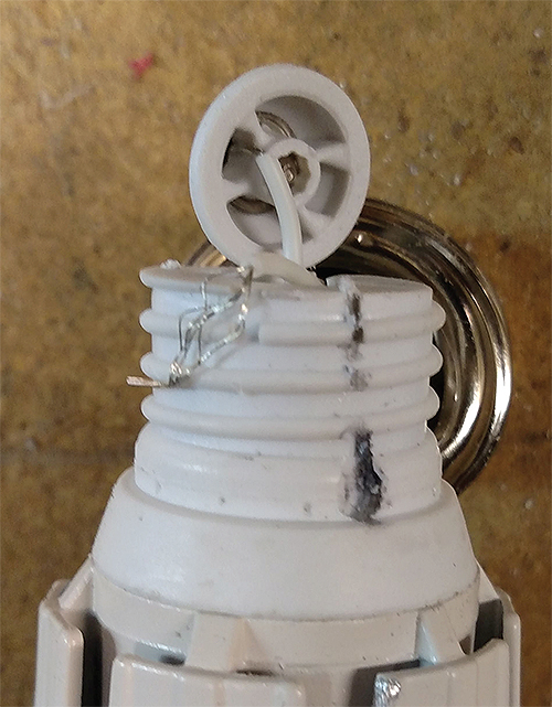
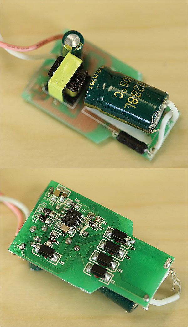
The ac/dc converter design is straightforward. The only non-SMD components are two big capacitors, a surge resistor on the input and a transformer. Connections from the board to the screw-base and to the LED board are through discrete wires, but the connection to the bulb foot contact was done by machine. The electrical connection to the metal screw threads, though, is simply a length of bare wire squeezed between the plastic housing and the inside surface of the screw threads.
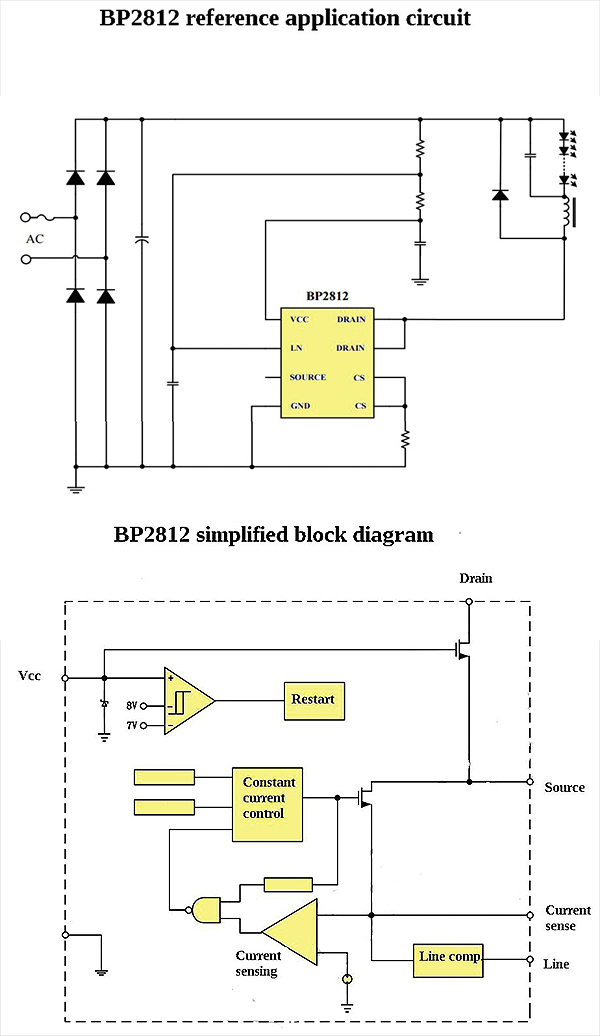
The electronics on the ac/dc converter are bare bones. The diode bridge on the input is four discrete diodes. There is a single IC on the board. It is a buck topology supply designed to provide a constant current and is made by Bright Power Semiconductor (BPS) in China. The chip, dubbed BP2812, incorporates a 600-V MOSFET. The spec sheet lists the chip operating current at 200 µA.
The “typical application circuit” listed on the BP2812 spec sheet comes extremely close to the actual circuit we found on the LED’s circuit board. Seven resistors go into simple networks that handle the Vcc voltage, sensing the buck inductor’s peak current, and regulating the input voltage to the IC. Five capacitors handle chores of ac line filtering, an ac by-pass for the Vcc pin and line-sense pins, and the buck topology. An in-line fuse cuts the power to the whole circuit in the event of too-high current draw.
Judging by graphics on the BPS web site, it looks as though BPS may have assembled the board itself. There are images there of example boards for a few other LED applications that look remarkably similar to this one.
It should be noted that the effect of temperature on LED operation doesn’t seem to be factored into the ac/dc converter. LEDs put out less light as their temperature rises. That’s generally not a problem for small temperature changes. The eye’s sensitivity to light is logarithmic, and the eye is not particularly sensitive to small changes in luminosity. It’s not unusual to see a 10% drop in LED lumen output as junction temperature rises from room temperature to 150° C.
But LED current can also be reduced at higher temperatures as a way of lessening the need for heat sinking. That said, there is no temperature sensing that we could see in the Home EVER bulb’s ac/dc converter. And there is no circuitry for dimming.
But all in all, the LED bulb probably works well in uses that don’t need a dimmable light.
Osram
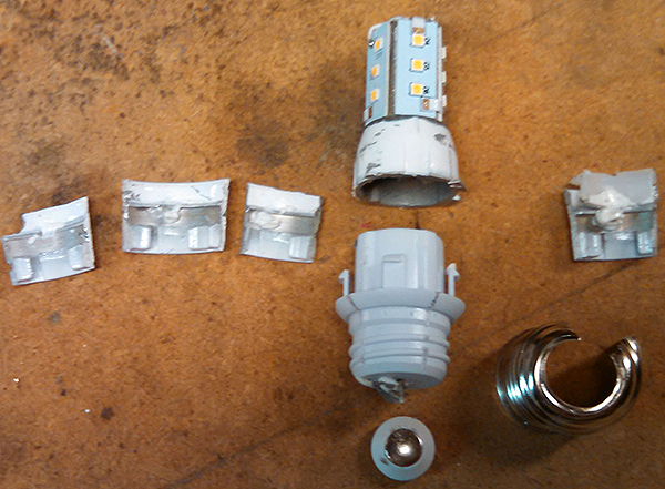
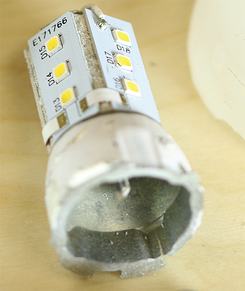
Osram Sylvania’s 60-W equivalent LED bulb is notable in that it has a relatively small, two-piece heat sink. One piece is a 1-in.-high pentagon-shaped tower that doubles as a backing for six LED boards, five oriented in a pentagon shape with the sixth sitting atop the pentagon tower. The other is a 0.75-in.-long cylindrical cast heat sink that apparently snap-fits to the upper part of the plastic dome housing the LEDs. The cylindrical cast heat sink and tower together weigh 1.3 oz.
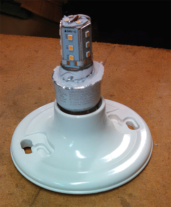
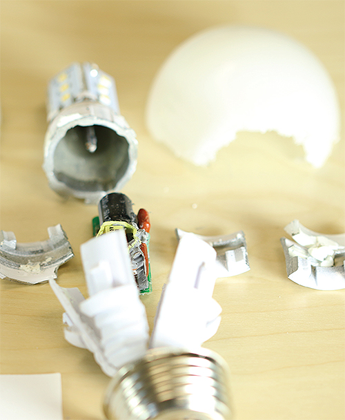
The base of the unit is a one-piece plastic housing that holds the ac/dc converter circuit board. Two wires connect it to the pentagon-shaped tower holding 18 LEDs, three on each face. The connections between the boards appear to have been reflow soldered. But the discrete wires between the circuit board and the LED assembly appear to have been hand soldered. Similarly, connections to the bulb base are discrete wires with one squeezed between the metal screw threads, the other a machine assembled to the bulb foot.
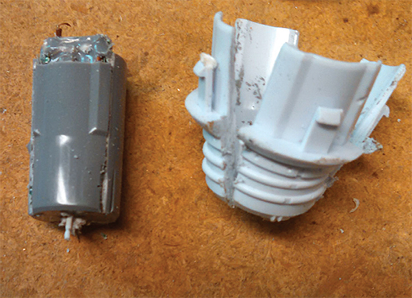
For reasons that are not completely clear, the designers of the Osram bulb chose to pot the ac/dc converter board. The relatively small heat sink in this board, compared to other designs we’ve seen, might indicate the potting is meant to improve thermal dissipation, though potting material doesn’t completely fill the empty space between the electronic components and the external shell. The potting did, however, complicate the process of deciphering the circuit.
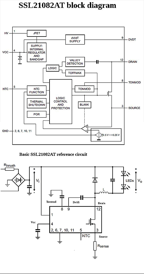
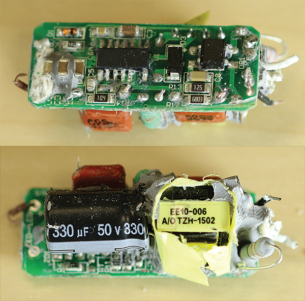
The main board for the Osram LED bulb is two sided. It contains two ICs, one a diode bridge for the ac input, the other an SSL21082AT driver IC from NXP Semiconductors. Features implemented on the NXP chip include dimming, over-temperature protection and LED over-temperature control, output short protection, and a restart mode in the event of a brown out. This IC has an integrated internal HV switch and work as a boundary conduction mode (BCM) buck converter.
BCM is a quasi-resonant technique used to enhance energy efficiency. The fundamental idea of BCM is that the inductor current starts from zero in each switching period. When the power transistor of the boost converter is turned on for a fixed time, the peak inductor current is proportional to the input voltage. The current waveform is triangular; so the average value in each switching period is proportional to the input voltage.
Energy stores in the inductor while the switch is on. The inductor current is zero when the MOSFET is on. The amplitude of the current build-up in the inductor is proportional to the voltage drop over the inductor and the time that the MOSFET switch is on. When the MOSFET is switched off, the energy in the inductor releases toward the output. The LED current depends on the peak current through the inductor and on the dimmer angle. A new cycle starts once the inductor current is zero.
3M
The 3M LED has a distinctive look thanks to the 2-in.-high white cylindrical column visible under its semitransparent plastic dome. The column is just a metal heat sink; it apparently has nothing to do with the dispersion of light.
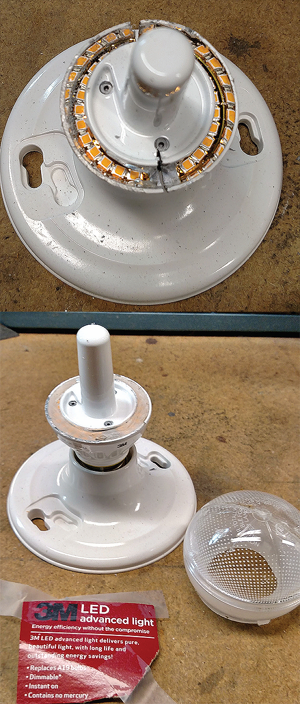
The LEDs sit on a flex circuit board attached to another 2-in.-high heat sink that also forms a support for the base of the bulb. A plastic sleeve goes on the bottom of the heat sink to hold the metal screw threads and support the foot contact at the bottom of the base. The heat sink plus column together weigh in at 2.4 oz.
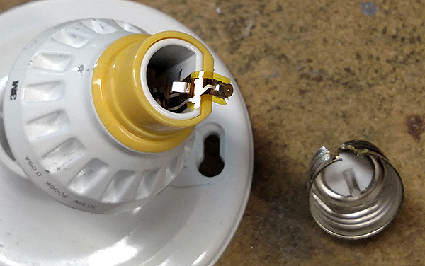
The flex circuit board holding the LEDs also holds the ac/dc driver circuit. It is a CL8800 from Microchip Technology. The reference design consists of the CL8800, six resistors and a bridge rectifier (a Fairchild device). Two to four additional components are optional for various levels of transient protection. Microchip’s reference design is quite close to what we found in the 3M bulb.
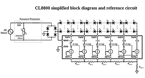
The driver circuit divides a string of 25 LEDs into two sets of five, one set of four, and one set of six. We’re not sure why 3M divided the number of string LEDs this way. Their orientation, however, is interesting. They sit on a ledge formed by the heat sink and are oriented straight up. The transparent carbonate globe fits onto the same ledge, so the LED light output is actually up into the edge of the plastic globe itself, rather than shining through the globe from the inside of the shell.
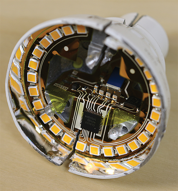
The LED driver circuitry is quite simple and laid out on the flex circuit without any potting compound to get in the way. According to the Microchip data sheet, six linear current regulators sink current at each tap and are sequentially turned on and off in a manner tracking the input sine wave voltage. The chip minimizes the voltage across each regulator when conducting, providing high efficiency.
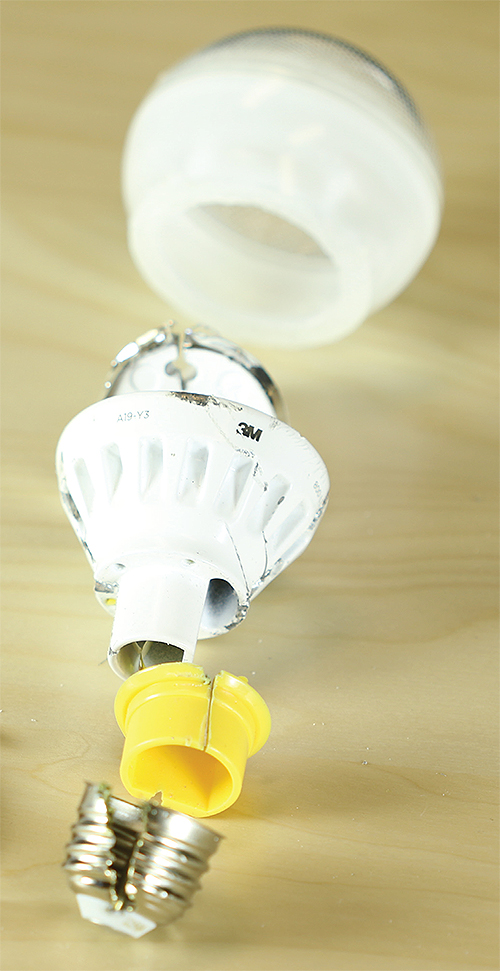
The output current at each tap is individually set by a resistor. An RC network, consisting of a resistor and three capacitors in parallel, on the input of the bridge rectifier provides phase dimming. Two other components handle transient protection on the connection to the ac line. In all, there are 13 discrete components on the flex circuit that make up the transient protection, phase dimming, and set the currents in the LED strings.
Feit Electric Co.
The bulb from Feit Electric had the oddest orientation for LEDs of any we examined. The 1 7⁄8-in.-diameter plate onto which the 36 LEDs mount is partly hidden in the assembled bulb by a circular plastic piece with a 1-in.-diameter hole in the middle. This piece mounts over top the LED plate. So, a look at the assembled bulb provides a view of the plastic piece and just five LEDs visible on the center of the plate below the hole in its middle.
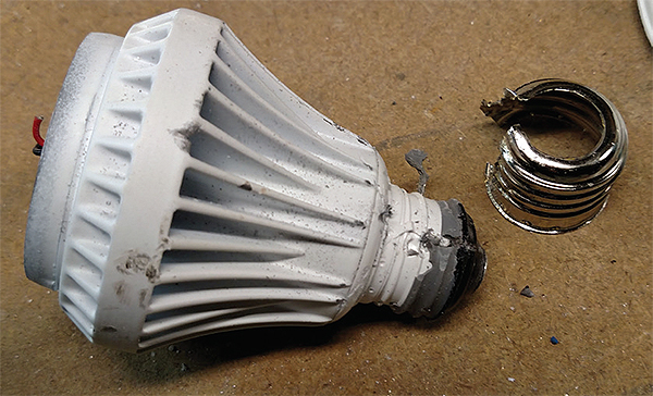
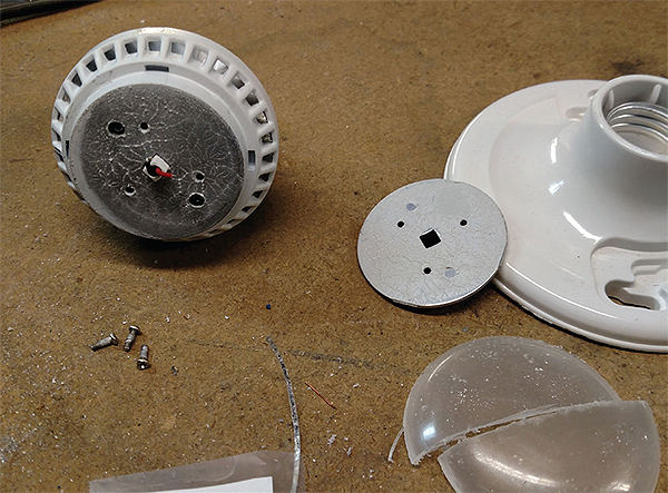
We are at a loss as to why Feit installed the plastic piece over top most of its LEDs. The piece blocks most of the light they emit. (We have no way of quantifying the amount of light getting through the plastic. But informal tests here indicate little of it penetrates.) So the vast majority of the emitted lumens come from the five LEDs in the center of the plate.
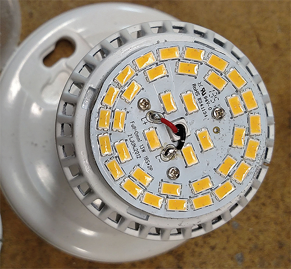
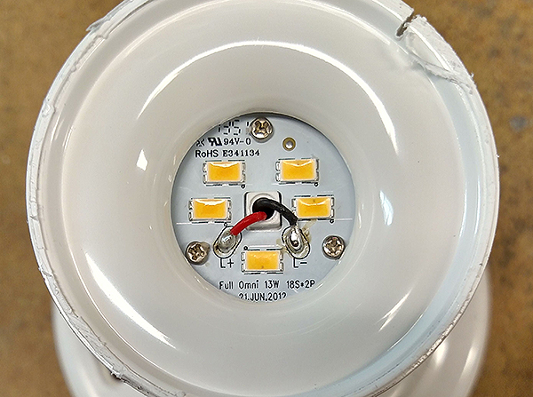
The rest of the bulb’s mechanical design is less mystifying. The LED plate mounts to the top of a hefty 3.8-oz cast metal heat sink with three screws. The heat sink serves as the main body of the bulb. The ac/dc converter circuitry fits in a plastic cylinder that slides into the base of the heat sink and attaches to it with two screws.
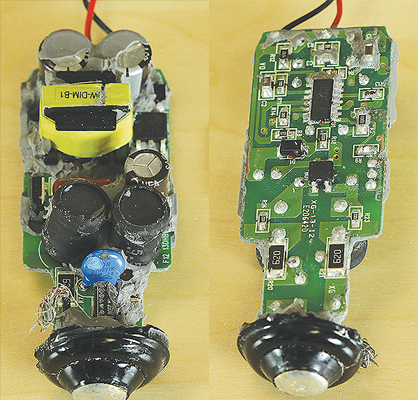
The electronics is potted into the plastic cylinder that serves as its housing. The potting material is extensive, filling the cylinder. It also doubles as a structural element supporting the screw base of the bulb and the contact foot. The circuit board holding the electronics is two-sided and extends back nearly to the foot of the bulb base. The negative lead to the board is held to the metal screw threads by the potting material. Two wires run from the board to the LED board and seem to be hand soldered there. The board itself is reflow soldered.
The potting material obscured some of the details on the PCB, but on the board are two power MOSFETs, a diode bridge chip, five large caps, transformer, and at least 22 discrete components comprised of resistors, small caps and diodes. The input bridge rectifier seems to be protected with a fusistor.
The main chip is an SSL2103T LED driver from NXP Semiconductors. The SSL2103 is basically a flyback converter that operates in combination with a phase cut dimmer circuit directly from the rectified mains. It implements dimming through integrated circuitry that optimizes the dimming curve. Drive outputs are available for resistive bleeder switching.
Though potting material obscures some of the connection details, the circuit seems to be close to that of NXP reference designs for the chip. The mains voltage is rectified, buffered and filtered in the input section and connected to the primary winding of a transformer. The transferred energy is stored in a capacitor and filtered before driving the LED chain.
The circuit board also includes two power MOSFETs. One seems to be part of a dimming circuit that divides and filters the mains rectified voltage to provide an input for the generation of the dimming curve. A bleeder drive output from the NXP chip drives the MOSFET to switch bleeder resistors that are involved in a timer for the dimming function. The other MOSFET is the main switch for the flyback transformer.

There is also a buffer circuit consisting of two capacitors and an inductor. The circuit stores energy to ensure the converter can transfer power continuously to the LED chain despite any mains power fluctuations. It also filters ripple current generated by the converter to keep down any mains-conducted emissions.
Finally, another portion of the circuit consists of a capacitor, a rectifier diode, a peak-current-limiting resistor and a protection zener diode and is used to generate an external VCC supply for the IC.
Philips Lighting Co.
One noteworthy point about the Philips bulb pertains to heat sinking. The other bulbs we examined had metal heat sinks ranging in weight from 1.3 to 3.8 oz. The Philips bulb manages to handle thermal issues without any extra heat sinking. The only component that spreads heat is the 2.5-in.-diameter disk onto which the 26 LEDs mount, 13 to a side. Moreover, you might expect that designers would stagger the LEDs on the disk such that they wouldn’t mount directly opposite each other—this mounting arrangement would also help spread heat. But the LEDs on either side of the disk sit directly opposite each other. It appears that LED heat just wasn’t an issue in this design.
One of the reasons why is the presence of a negative temperature coefficient (NTC) thermistor on the LED board. But it proved to be impossible to trace out the temperature compensation network exactly because the driver PCB has three layers, one hidden. Further complicating the analysis of the circuit is the fact that two six-pin ICs seem to handle the ac-dc conversion and neither is marked with either a manufacturer logo or part number.
Because the main ICs can’t be identified, we can only hypothesize about how the LED driver works. The presence of a transformer, two large capacitors and an npn power transistor (from STMicroelectronics) on the PCB would seem to indicate that the converter has a flyback design. Our guess is that the temperature compensation network is in the biasing of the switch providing current to the LEDs from the flyback transformer. Two transistors seem to handle the LED current. In all, we counted 32 small discrete components made up of resistors, diodes and capacitors. Rounding out the board components were a bridge rectifier chip and three other power capacitors.
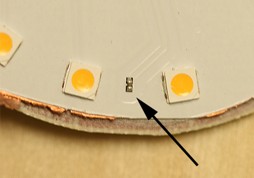
It turns out that the mechanical design of an LED bulb that contains no heat sink can be quite simple (and some might call it elegant). The Philips bulb is basically a plastic enclosure that encases the LED plate and driver PCB while also supporting the metal screw threads and contact foot.
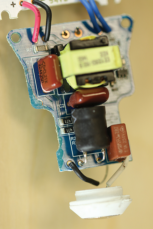
The form factor differs from that of other bulbs because of the two-sided LED plate. The Philips bulb isn’t so much a bulb as a disk. Rather than encasing the LEDs in a transparent globe-like enclosure, the Philips device presents a flat profile with plastic encasing the two-sided LED plate. The enclosure seems to just snap together over top the LED plate and driver PCB.
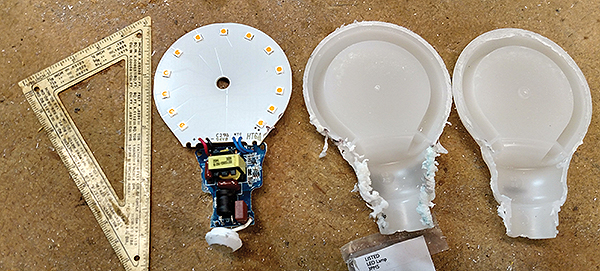
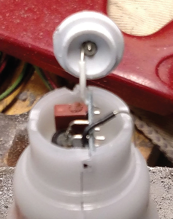
And because the Philips bulb contains no heat sink, it is quite light weight. But its disk-like outline might look a little weird to consumers accustomed to screwing things that are shaped like spheres into light sockets. And it beams most of its light out on the two sides defined by the orientation of the LED plates. It relies on diffusion by the plastic enclosure for lighting in other directions.


It would be interesting to see how much power they each draw in comparison. To see whether simple or sophisticated wins.
The Philips bulb can be had for 3.77 each in a 4 pack this is about 1/2 the cost of the others.
Philips 433227 10.5-watt Slim Style Dimmable A19 LED Light Bulb, Soft White (Pack of 4)
Sold by: Solicom Ltd $15.07 on amazon
I’ve been analyzing the lumen output and input power of the various popular bulbs. They are all pretty close in wattage, but some of the newer bulbs, like the 3/$10 GE ‘Stik Light’ bulbs are great for the price. Some designs like the 4-flow cree bulbs, run surprisingly cool, with a natural convection air-flow design. The Phillips disc bulbs are very good as well, running fairly cool.
It would be helpful to see the bulbs before they are disassembled.
A big problem with these lights is interference with AM, FM and DAB radios. Many types are so bad that when you switch them on, they completely block DAB radio reception so that the radio goes ‘off’ as soon as you turn on the light. They can also interfere with bluetooth and wifi, etc. Some RF spectral analysis might also be useful to see.
It would’ve been nice to have had a photo of all of them next to each other before tear down. Plus some lumens output measurements and whiteness of the light output (degrees K) plus current and actual measured power consumption and their expected life and price.
Which one won?
You have done a good job of evaluating the Bulbs. A lot of effort has been put in. It would be nice to have the efficiency and Power Factor as also the workable input voltage range for comparison.
The Feit bulb is ‘omni directional’, ls light is reflected of the bottom of the plastic piece, you can see a picture of it on Amazon, I found a higher power one that is similar,
Feit Electric Omni Directional 100W/15.5W LED Dimmable 1600 Lumens, click on the third picture in the description.
I have this exact bulb throughout my house. I can’t speak for the internals, but as a consumer it’s a great product, and it really is equivalent with a 100W incandescent.
What an interesting article.
But I have to confess that I am shocked to see that CREE, probably one of the best LED lightbulb replacement lamps available on the market according to my assessment, based on testing of most GE, Sylvania, Philips and Cree models, wasn’t part of this teardown comparison. Why? Is it because it’s only available through Home Depot?
Also I find it odd to see that this article doesn’t speak of the fact that Philips’ slim lamp can cause weird shadowing effects as it is not an omnidirectional lamp.
LED technology has come a long way from its humble beginning. It has always been by far the most economical and most efficient lighting technology in existence. Now they can be used in a variety of applications from indicating to illuminating.
However, while technical sophistication may seem savvy for ‘driving’ LEDs for lighting, so much of it is unnecessary and has many times contributed to higher failure rates.
Usage of electrolytic capacitors is standard in almost all electronics. Altho necessary, they tend to have modest to high failures within high electrical stress circuits and high heat environments. LED driver circuits utilize such capacitors which have been a major contributor to premature failures of LED lights, such as discussed in this article.
Adding to all of this circuit complexity and problems are RFI emissions, which is a cause of electrical interference in radio devices. There is also the erroneous philosophy that LEDs must be pulsed width modulated for best efficiency and proper color rendition. This is simply not true.
The actual LED is basically nothing more than a PN junction just like any other semiconductor diode. Thus the term “Light Emitting Diode” or “LED.” The LED itself will produce light by itself when an electrical current is passed thru it in the forward direction. There’s really nothing in the diode junction to burn out, so they can last a really LONG time. It’s the support circuits that usually fail – NOT the LED.
For the new LED bulbs to last a long time, it is imperative that simpler, more practical circuit designs be implemented to avoid such problems of premature failures and interference issues.
“….Cree models, wasn’t part of this teardown comparison. Why?’
Easy: We used bulbs that had the highest ratings from a Consumer Reports Magazine comparison. The five we looked at were the top five mentioned in the CR article. We had no idea whose chip was in each bulb before we started. We figured that looking at one or two wouldn’t give us much of a feel for what was out there, and looking at ten or more wasn’t practical for us. So looking at five was the pragmatic compromise.
As far as the weird shadowing of the Philips bulb, we were more interested in the electronics inside the bulb than in the emissions qualities.
The driver circuit divides a string of 25 LEDs into two sets of five,
one set of four, and one set of six. We’re not sure why 3M divided the
number of string LEDs this way.
There are three kinds of engineers in thei world, those that can count and those that can’t.
RFI emissions are a tricky bit. I have been doing a teardown of T8 linear tubes and have contacted design engineers, testers in countries outside of the US, and the FCC and have also referenced a plethora of sites such as this. The T8 I am testing is the Euri Lighting ET8-1140H (Irtronix) is not (tested and labeled) FCC compliant…yet it falls well under the FCC limits for compliance. When used without the existing 47 kHz ballasts from our fluorescent luminaires they are even better. I am not working in a testing lab…I am just a lowly ET who is testing the bulbs purchased from our lowest bidder. I have been pleasantly surprised…so far.
Update…these tubes have stray voltage on the heatsink, up to line voltage when installed either single or double end-fed configurations, ballasted or not (manufacturer recommended installation configurations).
Proceed with caution…
I just completed a teardown of a couple of FEIT electric 100W equivalent 15.5W bulbs that failed way sooner than they should have (started flickering obnoxiously). Although the overall design was not horrendous, I noticed two glaring issues that quite obviously led to the problems:
First, the LED board is connected to the heatsink with two screws and there is suppose to be thermal paste in between the bottom of the LED plate and the heatsink itself. When in use, I had noticed that the heatsink on the bulb never got all that warm, but the plastic of the bulb section seemed hotter than it should. Upon inspection, there was only a small dab of thermal compound placed on one side of the heatsink and the other side did not appear to even be making full contact with the LED base plate. As a result, I’d guess only maybe 15-20% of the LED base plate was in contact with the heatsink.One of the LED’s actually appears to have charred around the base — probably due to failure brought on by improper cooling. So, design fine, assembly poor.
Second, the power regulator board contains a TAICON 250V 22uF 105C C(BY)P electrolytic capacitor — which is swollen and bulging on the end. This is likely the source of the flicker. Although this is a high temperature (105C) electrolytic capacitor that appears to be intended for ballast usage and has a rated 10000hr life, I’m still certain it didn’t enjoy the temperatures it was likely subjected to thanks to the poor heatsink mounting. Personally, I would have preferred they had chosen a power supply design that didn’t require putting an electrolytic cap in this hig temperature a location in the first place. And, in any case, the 10000hr rated life (416 *DAYS*) of the capacitor will likely be the limiting factor in the life of this bulb in any case. In any high use location in a typical home, having the bulb on for 8 hours a day is not uncommon — which means that even WITH adequate cooling, this bulb would have exceeded the expected design life of the capacitor within approximately 3.5 years at 8 hour per day. Considering that the packaging on the box advertised this bulb as having up to a “22 year life” under normal usage, I find this unacceptable. Unless the “normal usage” for the bulb was only 1.25 hours per day, the rated life of the capacitor would have been exceeded FAR sooner.
Somewhat less than happy about the quality of the FEIT bulb I purchased.
Second,
Bought some Feit 100W equivalent, 1600 lumen LED bulbs at Costco. Four for $16,.
Very similar design to the one in this teardown. 40 LEDs in two concentric rings on the aluminum disk, driven at 56vdc. The driver is based on the AL1696 chip and is dimable. Still has an electrolytic capacitor (330uf, 80v), but it is now rated for 130C.
I like its 3000K soft white color better than most 2700K warm white LEDs I’ve bought (esp,. Phillips). The color of all LED bulbs has improved a lot in the last few years.
Feit also has 60W eq. bulbs you can find for about $1. I don’t expect these inexpensive bulbs to last for a decade – but they don’t need to at these prices.
Against common expectation, my own experience is that the LED chips *do* burn out, and are the cause of dead LED bulbs at least as often as dead driver boards. Of 3 dead Cree bulbs two have a single dead led. I suspect this is due more to spikes than just heat. Having ten or so LEDs in series is a good way to decrease your MTBF.
Interesting bit about LEDs themselves burning out. Every bulb I’ve seen so far has at least a portion of its LEDs in series, but that is understandable if, as a designer, you expect the driver to puke out long before one of the LEDs.
To drive LEDs off the mains requires a transformer, bridge rectifier and a resistor! That’s all. The over complication makes for poor reliability when LEDs have an MTBF of around 200 years.
What is the wattage capacity & voltage per led in 9 watt led bulb?
Feit has updated their design twice since this article. I bought a bunch of TrueCcolor series A19 810 lumen bulbs with a finned heatsink (now discontinued). There were 8 bulbs mounted horizontally and 6 failed within two years. My theory was that a lightning strike/surge killed the drivers. They were not in an enclosed fixture and in fact heat was permitted to escape. I will recap the driver and see if that taicon cap (22mF /105C /250v) failed.
The newest generation of Feit true color which I received as a warranty replacement doesn’t have an external heatsink at all. I’m curious what innovations have taken place to address thermal dissipation in the latest LED bulbs?
It would be interesting to tear down Soraa MR16 bulbs. In my opinion these are technological marvels. The inventor got the Nobel prize.
Also, to those that think the LED chips last forever. I have heard from experts that the yellow phosphor can delaminate or bubble over time due to heat. This leads to dimmer output, color shifts, and even weird shadows if it peels up unevenly. However there’s a chance that this issue was addressed in recent years and won’t crop up? So I’m not sure if it’s a concern anymore.
I do not know if it’s just me or if perhaps everybody else encountering problems with your blog.
It seems like some of the written text on your posts
are running off the screen. Can someone else please comment and let me know if this is
happening to them too? This might be a issue
with my browser because I’ve had this happen before.
Thank you
I’m disassembling several LED Light Bulbs, they all failed within a short time! They lasted much less time than an ordinary old fashioned Light Bulbs! Most of them failed because the Electrolytic Capacitor blew up due to heat and poor design! Few of them are very elegant in design and should not stop working, but something failed! I was able to power most of the LEDs with 12V, after removing the segments from the original housing. Couple individual LEDs are not working – that is why the bulb stopped working – I think. I would encourage people to disassemble broken or new LED Light Bulb. (Please take great care, using gloves and eye protection… I’m not responsible for your own safety!) It is educational and my interest knowing what works and how, why is this there or not… is richer just by examining them! They are much more complicated than they need to bee and I have them installed everywhere in my house, saving some money – but it was much more expensive just 2-3 years ago than today, putting LED lights in your home. The manufactures have created newer and newer ways to save money on their end as well as for us, the customers, but it will continue and lots of new technology is coming near you, that will make LEDs look like the old fashioned Light Bulbs! The first “new LEDs” will cost much more, but they don’t get as hot and will consume less power! Look at few articles, like this: https://qz.com/146761/forget-led-bulbs-the-future-of-interior-lighting-is-lasers/ or http://luxreview.com/article/2016/02/led-inventor-bets-on-lasers-to-replace-leds …. just Google it with something like this: “what will replace led light bulbs”.
What is the value of resistance connected at the first input of 230V AC to the LED Bulb ?
In the end models after 1 year diodes produce 50% of initial light. If not dead.. Additional phosphor is transparent color is bluish. temperature is near of burn. Please make leds life easy they are good and for ever if work at 50% from beginning. I always open the lamps and correct power. If not possible -divide leds to two parallel branches. If not possible just connect lamps in pears serial and have 80% of each.
LEDs go at least 10 years before losing substantial light, not one year. Ditto for trending toward the blue part of the spectrum. And not all LEDs trend toward the blue part of the spectrum. When the Dept. of Energy tested LEDs, they found that LED bulbs actually shifted in color over time less than other lighting technologies they tested: https://www.energy.gov/sites/prod/files/2017/04/f34/lsrc_colorshift_apr2017.pdf
This is written a few years later than the originals. It would seem that many LED bulbs now use a capacitor as a current limiting reactance, feeding a bridge rectifier, going to an electrolytic smoothing capacitor, feeding a long string of LEDs. High value resistors across both capacitors bleed of voltage when turned off. Good bulbs include high voltage Zener diodes across the LEDs to protect the electrolytic in the event of a failure of one of the LEDs. Very simple, lower cost, and very effective.
LED bulb manufacturers should be doing what Phillips did.
Heat equals wasted energy and most led bulbs with heat sinks get so hot you can’t touch the base which means ALOT of wasted energy.
The Phillips bulb is cool to the touch after running for hours and it doesn’t suffer from the flicker that most others have.
The mistake many make is not using a large enough capacitor on the output of the bridge.
The key to a stable and flicker free led bulb is good filtering of the DC power which costs money.
This is why cheal bulbs flicker and fail early while expensive name brands are flicker free and last for years
I just dissected an LED bulb that intermittently flickered or went off completely . From what I can see of the circuitry it appears to be a stepdown transformer a rectifier and a filtercap but I have not cut into the base metal or the poly bulb yet. I dont understand the need for full wave rectification or regulating. Unfortunately I destroyed the brand name with my angle grinder.