
by Hadi Ebrahimi-Darkhaneh, Texas Instruments
For applications that employ temperature monitoring systems, measurement accuracy is a prime concern. Temperature sensors are affected by a variety of factors, including environmental conditions, manufacturing process variations, poor assembly, and nonideal biasing components. External components connected to temperature sensors (such as the power supply, an analog-to-digital converter [ADC] and filters) can also significantly impact overall system performance.
Thermistors, or devices that vary resistance based on changes in temperature, are commonly used to monitor temperature in systems. Power-supply variation is a root cause of erroneous thermistor readings. One popular method to negate this effect and improve sensor accuracy is ratiometricity. References [1] and [2] introduce the concepts of absolute and ratiometric measurement methods, while references [3] and [4] present theoretical analysis showing the impact of undesired circuit component variations on accurate sensor readings.
A ratiometric measurement can eliminate interference in the power supply. In this method, the measured quantity sought after is the ratio of two quantities that typically exhibit interference. System calibration may also be required to further reduce measurement errors and improve system accuracy.
This article presents a comprehensive error analysis of a temperature sensing system using the absolute and ratiometric approaches, performing a worst-case error analysis using negative temperature coefficient (NTC) and positive temperature coefficient (PTC) thermistors; applying single-point calibration to offset measurement errors at room temperature; and presenting data that compares both measurement methods for both thermistor types.
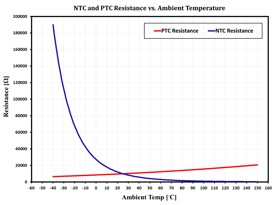
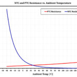
Figure 1 compares the NTC and silicon-based PTC thermistors used throughout this study in a temperature range from -40°C to 150°C.
Theoretical Concepts
As mentioned previously, power-supply variation is a root cause of measurement errors in thermistors; ratiometricity can negate this effect and improve sensor accuracy. In ratiometricity, the quantity under measurement is proportional to the ratio of two signals rather than to an absolute reference signal. In other words, the signal of interest is measured with respect to another signal (such as a voltage or current source) to which it is proportionally related.
Figures 2 and 3 show two common biasing methods for a thermistor in a temperature sensing network. Figure 2 represents a simplified view of the absolute measurement approach.
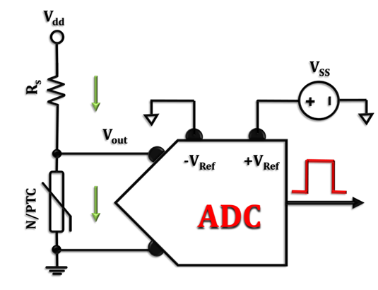
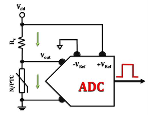
Figure 3 reconfigures the same sensing network for ratiometric measurements.
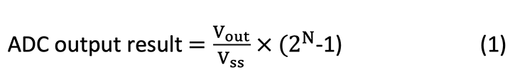
Corresponding to each method, Equations 1 through 5 describe the relationship between the different circuit components of Figures 2 and 3, and the ADC output result. These equations also describe the relationship between the divider network output signal and the ADC’s output result.
In Equation 1, N denotes the ADC’s resolution bit, and Vss is the independent reference voltage:
Equation 2 expresses the temperature-dependent signal across the thermistor (Vout):

Substituting Vout in Equation 1 with the actual term given by Equation 2 yields Equation 3:
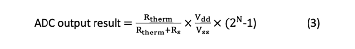
From Equation 1, you can see that the measurement accuracy of the absolute method (Figure 2) is susceptible to external variations and thermal drifts from three different sources: Rs, Vdd and Vss.
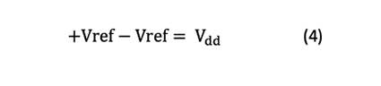
In the ratiometric approach shown in Figure 3, the reference voltage is picked from the main supply voltage (Vdd) instead of using an independent external voltage source (Vss). Assuming that the wires connecting Vdd to the reference input and ground terminals (±Vref) have a minimal impedance effect, Equation 4 expresses the reference voltage of the ADC as:
Substituting the new reference voltage from Equation 4 into Equation 3, Equation 5 simplifies the ADC output result:

Equation 5 shows how the ratiometric technique completely illuminates the dependency of the ADC output result on the Vdd and Vss voltage sources.
To verify measurement accuracy, three nonideal components are used for Vdd, Vss and the current-limiting resistance (Rs), assuming that:
- The supply voltage has some ±DC offset proportional to the nominal value of the voltage source.
- The supply voltage has some dependency on the ambient temperature, in which the voltage drift is given by a constant temperature coefficient.
- Similar to the voltage source, Rs also has some fixed tolerance, as well as temperature-dependent drift (given by a positive temperature coefficient in Table 1) to describe the actual behavior of Rs under different ambient temperatures [4,5].
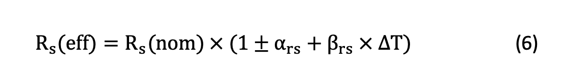
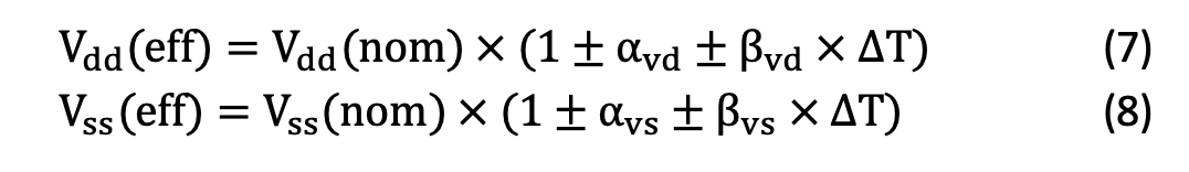
Although in a practical situation these components may show somewhat nonlinear behavior, for simplicity I have only considered linear variations. Equations 6, 7 and 8 are the mathematical models describing each component’s dynamics.
In Equation 6, the Rs resistor from different vendors comes with a ±max tolerance (as a percentage of the device’s nominal value) and a temperature coefficient. All of these parameters can be easily found in the device’s data sheet or other supporting documents.
Equations 7 and 8 express the common behavior seen in most nonideal power supplies and voltage regulators. For instance, in a band-gap reference voltage, there is some ±DC tolerance and slight temperature-dependent drift that is normally expressed by a thermal coefficient.
Please note that resistors made of different materials by different manufacturers may behave differently. This study only presents the typical behavior seen in a ceramic resistive component. Also, resistor tolerance is a key factor and will affect cost. For example, a 2-kΩ ceramic resistor with a ±1% tolerance costs more than one with a ±5% tolerance made by the same manufacturer.
Table 1 lists the parameters used for the modeling simulations in this article. 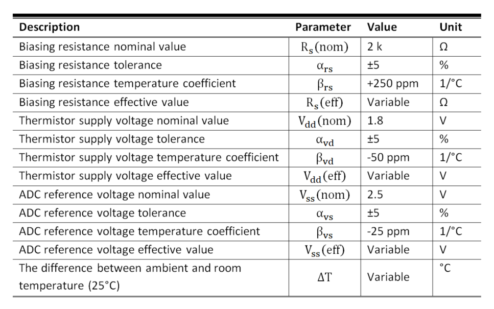
Results and Discussion
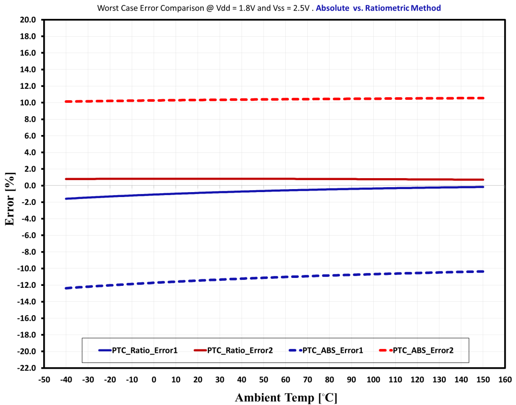
Figure 4 compares the worst-case measurement error for the absolute measurement, employing NTC and silicon-based PTC thermistors (Figure 1) in the voltage divider network of Figure 2. From Figure 4, you can see the nonlinear error profile vs. the ambient temperature using an NTC thermistor. This nonlinearity is attributed to the nonlinear nature of the NTC thermistor shown in Figure 1.
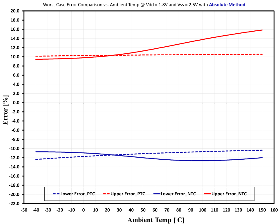
Conversely, the result obtained for the case with the PTC thermistor indicates a roughly constant error for the entire measured temperature range. This behavior is mainly associated with the linear characteristics of the silicon-based PTC thermistor.
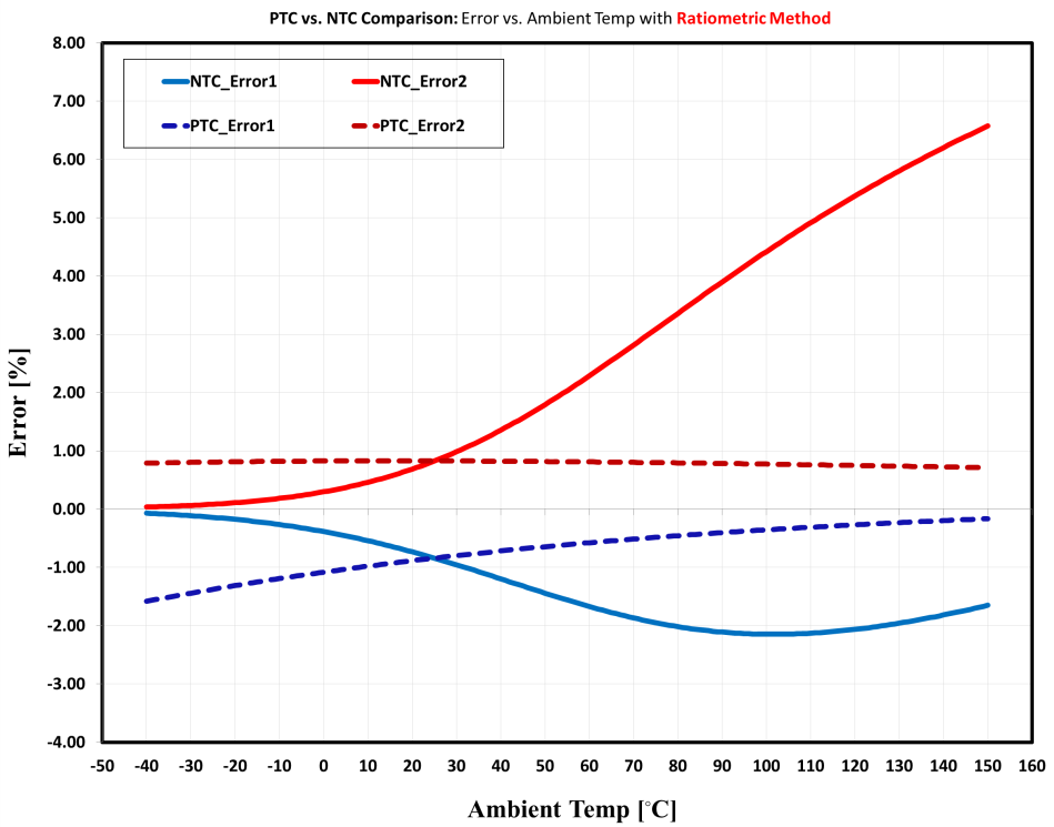
In a similar effort, system characterization was carried out using the ratiometric method. The circuit configuration of Figure 3 was used to evaluate the system error performance with both NTC and PTC thermistors.
Figure 5 shows the simulation results captured for the temperature measurement error using the ratiometric approach, which clearly indicate better measurement accuracy with the Si- PTC thermistor. You can see the magnitude of the error collected for different ambient temperature. The predictability (constant error profile) for the PTC looks much better compared to the NTC.
Figures 6 and 7 compare the errors between the ratiometric and absolute methods for each thermistor type. Figure 6 compares the measured temperature error using the NTC thermistor in both the absolute and ratiometric circuit configurations. As expected, the ratiometric method produces a lower system error under the exact same test conditions given the cancellation of external supply variations.
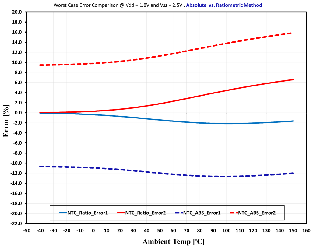
Figure 7 compares system errors with the PTC thermistor used in both measurement methods. One great advantage shown in Figure 7 is the predictability in the error response compared to the NTC thermistor. This can be a great argument for using silicon-based PTC sensors for cost-effective calibration, such as single-point calibration.
In the instrumentation industry, sensor calibration represents a significant portion of operational and labor costs. The sensor calibration becomes more of a bottleneck if a sensor produces unpredictable/nonlinear errors that cannot be offset easily with simple calibration techniques. Single-point calibration [5] is a more cost-effective (and common) approach for sensor error reduction.
Consider the worst-case error results in Figures 4 and 5. To compare the system error profile after one-point calibration, add a ±10% offset at Ta = 25°C and replot the results. Figure 8 compares data corresponding to single-point calibration.
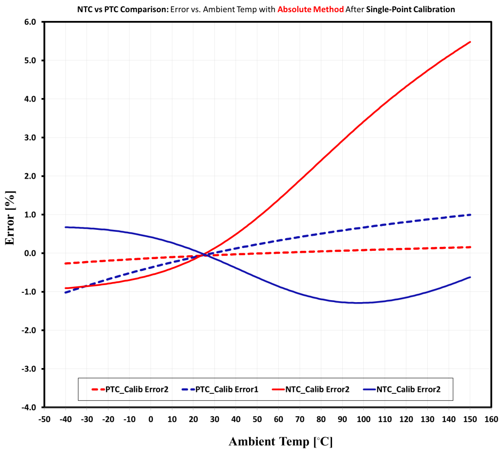
As you can see, the system measurement error using the silicon-based PTC thermistor is much lower than the NTC thermistor. Once again, this advantage is mainly attributable to the linear property of the silicon-based PTC thermistor. Therefore, for applications where the use of an independent external supply is inevitable (such as remote sensing), single-point calibration can reduce errors and improve sensor readings.
As shown in Figure 8, single-point calibration is very effective when using a linear PTC thermistor. This method, however, does not work well using an NTC thermistor due to the nonlinearity.
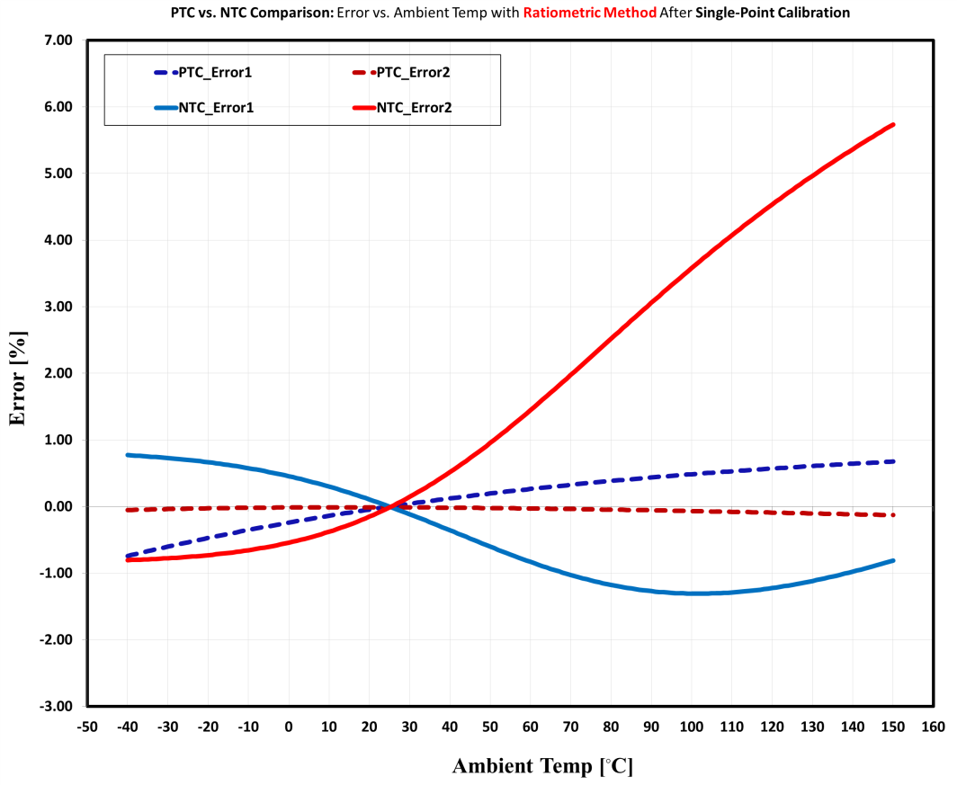
Figure 9 shows the error profile of the ratiometric method after one-point calibration. At Ta = 25°C, applying proper ±DC offsets reduces the measurement errors. For the linear PTC, the error has substantially declined for the entire range of the temperature under measurement. For the NTC, the measurement error does not show notable improvement. This is, again, due to the nonlinear nature of the NTC thermistor.
Conclusion
Captured results showed the effectiveness of using the ratiometric approach to improve system measurement errors. The silicon-based PTC thermistor offers much better performance in terms of precision and predictability. Results of the worst-case error profile caused by different component variations and under different test conditions show that the linear PTC thermistor produces a constant error profile for the entire temperature range in both the absolute and ratiometric methods. In contrast, the NTC thermistor demonstrates unpredictable error characteristics in both methods.
One-point calibration is a cost-effective and less complex approach for reducing system errors. When using single-point calibration, the PTC thermistor has an excellent error profile and can be considered a reliable design solution.
For more information on linear PTC thermistors, read my first article here or review the TMP61 on TI.com. see http://www.ti.com/product/TMP61.
References
- Analog Applications Journal: Ratiometric measurements in the context of LVDT-sensor signal conditioning
- Application report: Effect of resistor tolerances on power supply accuracy
- White paper: Voltage measurement accuracy, self-calibration, and ratiometric measurements
- Journal of Atmospheric and Oceanic Technology: Sensor and electronic biases/errors in air temperature measurements in common weather station networks
- Clinical Chemistry: Theoretical aspects of one-point calibration: causes and effects of some potential errors, and their dependence on concentration
Leave a Reply