
Measurements made on power analyzers may differ from those on another because different manufacturers employ different settings and wiring assumptions.
KEN JOHNSON, TELEDYNE LECROY
POWER ANALYZERS have been manufactured for many years and are used in a wide variety of applications. Often, the settings and preferences dialed in from the front panel can significantly impact measurements. Or the instrument has “legacy” capabilities that may not be well understood. In that regard, it can be useful to review how to set up Teledyne LeCroy’s Motor Drive Analyzer (MDA) to see results consistent with a Yokogawa Power Analyzer (YPA) and to explain why the results will be different in some cases.
First, for proper power analysis, one must determine a measurement period within which all calculations take place. Both the MDA and YPA use a “Sync” signal to determine the measurement period. In both cases, the Sync signal can be low-pass filtered to reduce the chances of finding an incorrect measurement period.
For a nearly sinusoidal (e.g., low-distortion) signal, both instruments should find the same measurement period with the same LPF cutoff selections, though the MDA offers a wider variety of selections.
The MDA also permits adjustment of hysteresis (band), allowing user-defined control of the software’s ignoring of non-monotonic factors that interfere with the measurement period calculation. Such control can be useful for signals that have higher distortion (e.g., brushless dc six-step commutated signals) or signals that have high distortion during high stress or failure events.
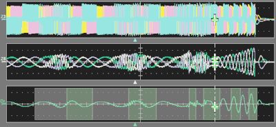
Note the MDA also permits display of the filtered Sync signal with a measurement period overlay, rendering the Sync signal settings easily understandable.
Finally, the MDA applies the Sync filter and hysteresis settings as a post-acquisition software process, while most power analyzers apply Sync filtering and hysteresis settings to the waveform during the acquisition. Thus, in the MDA, it is possible to make changes post-acquisition whereas this is not usually possible with a power-analyzer instrument. Combined with the Sync period overlay, one may use MDA post-acquisition processing to fine-tune the filter and hysteresis settings for best results without having to take a new acquisition and lose the acquired data.
The apparent power equation
YPA users may measure apparent power (S) by selecting any of the following equations in its setup menu:
Vrms× Irms: Same as provided by Teledyne LeCroy.
Vmean× Imean: Product of rectified mean values calibrated to the RMS values.
Vdc × Idc: Product of simple averages of the voltage and current.
Vmean × Irms: Product of the voltage’s rectified mean value and the current’s true RMS value.
Vrmean × Irmean: Product of the voltage’s and current’s rectified
mean values.
The MDA performs only Vrms× Irms of apparent power. To correlate power values from the YPA to the MDA results, set the selection for apparent power calculation on the YPA to Vrms× Irms.
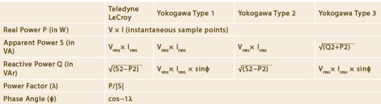
Teledyne LeCroy provides one method for calculation of power values whereas Yokogawa provides three different methods that return different results. For perfectly sinusoidal (zero-distortion) waveforms, it is possible to measure the phase angle ϕ between the voltage and current sinusoids. However, it is not possible to measure the phase angle ϕ when the waveforms are distorted (e.g., PWM drive output waveform). Therefore, the Teledyne LeCroy method or Yokogawa’s Type 2 method are the only methods that demonstrably produce accurate results for reactive power (and therefore power factor and phase angle) with distorted waveforms. (Both also produce accurate results with sinusoidal waveform).
Yokogawa’s power analyzers offer the Type 3 method on models with the harmonic measurement-mode option. This option appears to enable definition of a fundamental signal from one of the PWM signals using a PLL source. Then, the instrument determines phase angle by comparing the fundamental voltage and fundamental current waveforms, with power determined for the fundamental and each harmonic through “N” harmonics. This technique should provide a result similar to that from the Teledyne LeCroy Harmonic Filter setting = “Fundamental” or “Fundamental + N,” provided the hardware PLL response in the YPA can accommodate any change in period of the measured signal during the acquisition window.
Note that the YPA always calculates real power, P, correctly in all cases. If this is the only power value of interest, then all methods are suitable. However, to correctly calculate S, Q, λ, or ϕ, one must choose the correct YPA measurement method (if more than one is offered).
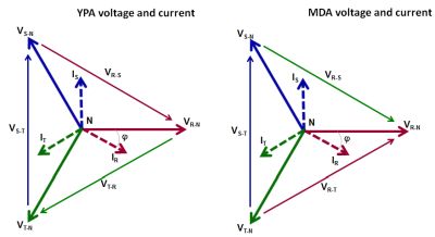
The YPA calculates per-phase power using the same equations as total three-phase power but does so on one phase at a time. The Yokogawa Type 2 method with apparent power setting = Vrms× Irms always correlates (assuming that the YPA can obtain a proper Sync period) with the MDA when using three-phase, four-wire (three voltages, three currents) wiring configurations with line-neutral or line-reference voltage probing.
However, if using line-line voltage probing, then per-phase power calculations in the YPA will be unbalanced and incorrect, though the three-phase total will be correct. The reasons for the differences are as follows:
The Yokogawa three-phase, three-wire (three voltages, three currents) wiring configuration is natively defined as a two-wattmeter setup. This is beneficial in that switching from a three-voltage and three-current measurement to a two-voltage and two-current measurement requires no re-connection of wires to the YPA. However, it also means that the line-line voltages and currents are incorrectly associated with each other on a per-phase basis.
The Teledyne LeCroy three-phase, three-wire (three voltages, three currents) wiring configuration also uses a two-wattmeter method for total three-phase power calculations. However, the MDA maintains the correct per-phase vector relationships to obtain proper per-phase calculations. The MDA simply inverts one of the voltage waveforms for the total three-phase power calculation.
The voltage associations made by the YPA have no impact on the total three-phase power (real, apparent, or reactive), phase angle, or power factor because the vector (voltage and current) relationships defined in their wiring setup are the correct relationships for the two-wattmeter method used to calculate their total three-phase power.
Both instruments can perform a line-line to line-neutral conversion (referred to as a delta-star conversion by Yokogawa, an extra-cost option). However, while the MDA will return accurate per-phase power calculations for P, S, Q, λ, and ϕ with this type of conversion, the YPA will return correct per-phase power calculations only for P.
The practical impact of the Yokogawa wiring configuration is that the voltage and current pairs all have different phase relationships (which is what leads to the incorrect per-phase power calculations).
Steady-state vs. dynamic events

The YPA calculates a mean steady-state power value over a normally short acquisition time (several cycles). There is an option for boosting the update rate for the mean-value calculations, but it is still a mean-value calculation over a defined period of time or number of cycles. The Sync period is determined through a PLL circuit programmed into an FPGA, which has a limited ability to lock onto widely varying speeds, dependent on the PLL loop bandwidth. In general, there is no practical limitation on a steady-state signal with a slowly changing measurement Sync period. Thus, the YPA is good for measuring mean values of power in steady-state (constant load, torque, speed, etc.) operating conditions.


The MDA can acquire short records and calculate mean power values for display in a table. Recall the Sync period is determined using a software algorithm. However, it can also make accurate measurements under dynamic operating conditions or loads because it lacks the operating limitations of a power analyzer instrument.
If the load is dynamic, it is quite possible a power analyzer instrument cannot provide a meaningful result. First, ensure correlation on a simple, static, steady-state load condition, and then attempt correlation with something more dynamic. If one cannot correlate results during dynamic operation, it is likely because the power analyzer instrument cannot accurately determine or verify Sync period, which is not typically a limitation of the Teledyne LeCroy MDA.
It is easy to correlate results from a Yokogawa Power Analyzer instrument to a Teledyne LeCroy Motor Drive Analyzer. The MDA provides more visual feedback on its operation, especially in accurate calculation of the Sync measurement period, which is vital to accurate power measurements. In some cases, a YPA has different settings or makes different wiring assumptions that lead to different results, which can be easily understood once they are known.
References
Teledyne LeCroy motor drive analyzer
Leave a Reply