
Compared to the LED bulbs of only a few years ago, modern-day versions are simpler and assembled via more automated methods.
Leland Teschler, Executive Editor
If you tore down an LED bulb manufactured a few years ago you’d likely find evidence of hand soldering a bit of kludgy design practices. We found both these practices in evidence when we examined LED bulbs back in 2015. We took bulbs from several manufacturers that all received the highest rankings from Consumer Reports. Several of them used rubber-like potting material apparently to both add stability to the screw threads and to help manage thermal dissipation.
A number of these mass-produced bulbs also displayed evidence of hand soldering. The most typical
location was in making a connection between the LED plate and the circuit board holding the bulb electronics, but some bulbs contained other instances of solder globs that looked as though they had been done by hand.
Back then, it was also common to see bulbs carrying sizable heat sinks. Many of the bulbs we looked at had metal heat-spreading components weighing in at a few ounces. And the circuitry driving the LEDs tended to be comprised of at least a dozen discrete components placed around the LED driver IC.
Things have changed quite a bit in four years. We recently procured a new batch of 60-W equivalent LED bulbs to see the progress since 2015. Like the last batch, these, too, were selected because they all got high ratings from Consumer Reports.
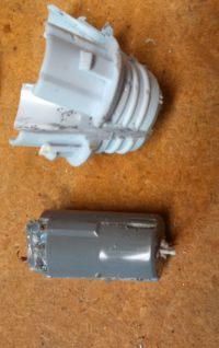
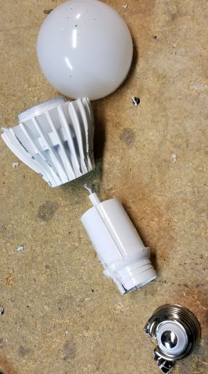
First consider the EcoSmart A19 LED bulb, which is assembled in China but comes from the Lighting Science Group in Florida. This 9.5-W bulb illustrates how simple LED bulb electronics can be so long as the bulb needn’t be dimmed. Cut away the translucent plastic cover and you’ll find a dozen LEDs sitting on the standard metal plate. The plate attaches to the bulb’s plastic housing via two Philips screws and to the PCB electronics via two connectors.
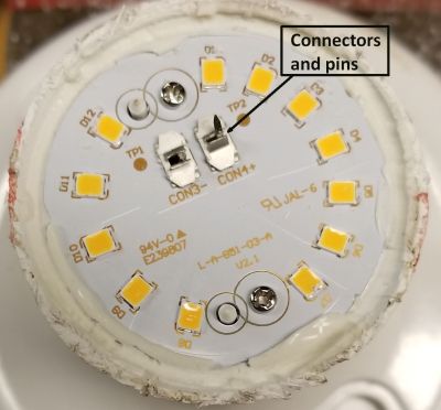
The connectors are worth a comment. They are simple and apparently inexpensive. They make a connection when metal posts on the PCB are pushed through them. They also seem to be designed for one-time use, fine for an LED bulb.
Simple though they are, these connectors are in contrast to the typical LED plate connection scheme we found in Chinese-made bulbs four years ago — the typical means of electrical connection was via soldered wires.
Also interesting are the methods used for connecting the electronics to the bulb base contact and to the metal screw threads.
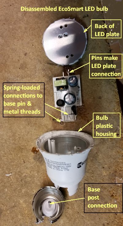
A press-fit connector makes contact with a metal post extending up from the base contact. The metal screw thread connection is via a metal strap that puts a spring-load against it for contact. The metal screw threads and base post are one assembly that presses on to the plastic housing that supports the translucent bulb and the PCB.
The simple configuration of the bulb base contrasts with what we typically found on LED bulbs in 2015. It wasn’t uncommon to find the metal screw threads supported mainly by potting material rather than by the plastic housing. In some bulbs the metal threads didn’t even touch the plastic housing. The potting did all the work. Similarly, the base contact on some bulbs was separate from the metal screw threads. And electrical connections to the base and to the metal screw threads tended to be via discrete wires.
The electronics for LED bulbs that don’t allow dimming can be simple. In the case of the EcoSmart bulb, a single IC (BP9916D) from Bright Power Semiconductor in China handles LED driving chores. It is a buck constant-current device and contains a 500-V power MOSFET for handling LED current.
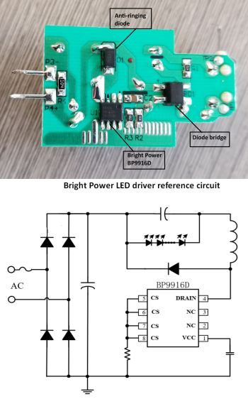
The circuit we found on the bulb PCB is basically the same as the reference circuit on the BP9916D data sheet. Three capacitors, one inductor, a diode bridge, one resistor, one discrete diode, and a fuse for safety are the basic circuit components. There are an additional three resistors that seem to be there as part of a test circuit. The main resistor is a sense resistor used to convert the buck converter from a voltage-output to a current-output device. The discrete diode seems to be there to head off any ringing from the switched inductor/capacitor.
A point to note about the electronics is that the only heat sink is the metal LED plate itself. The PCB fits in the plastic housing via plastic slots. There is a metalized area on the inside of the housing, but it doesn’t touch the PCB – it’s probably there for EMI shielding.
Bright Power doesn’t provide any details about the internal circuits of the LED driver chip. One detail it does provide is that the chip operates in critical conduction mode, meaning that the current in the inductor goes to zero before the next switching cycle initiates. Circuits that operate this way generally include a means of sensing when the inductor current hits zero, and this sensing usually takes place through a small sense winding used to show when voltage on the winding has dropped to near zero. However, a point to note about the Bright Power chip is that it doesn’t need a sense winding. The data sheet mentions something about a patent-pending MOSFET driving technique, which may have something to do with its ability to operate in critical conduction mode.
Sylvania LED bulb
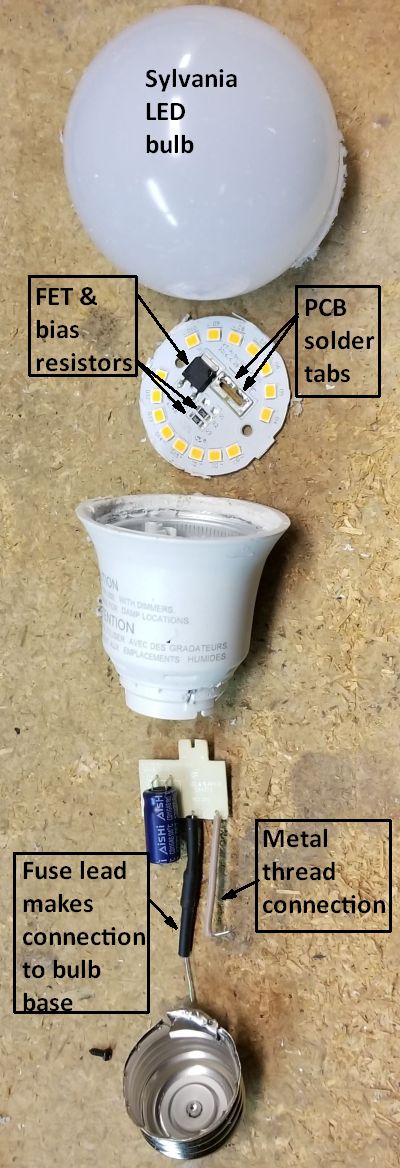
We now turn to another undimmable bulb, this one an 8.5-W, 2,700 K unit from Sylvania. If there was a prize given for the simplest possible LED bulb, this one might be a winner. It has the fewest components we’ve ever seen in a bulb recommended by Consumer Reports. It uses discrete wires to make a connection to the bulb threads and base, but the wire to the bulb base isn’t really a wire. It is actually a leaded fuse. So Sylvania cleverly used the fuse leads to take the place of the wire they’d otherwise have needed to get to the base.
As on the EcoSmart bulb, the PCB on this one slides into a plastic carrier. It also connects directly to the LED plate through two tabs which are soldered.
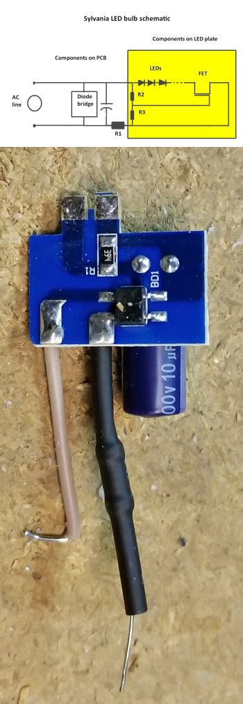
The LED driver circuit is dead simple. There’s no driver IC. Instead, what you find is a diode bridge rectifier and filter capacitor which feeds power to the LEDs. LEDs typically get power from a constant-current source because the LED light qualities vary with the current they carry. And there does, in fact, seem to be a current source in the Sylvania bulb. But it is a simple current source. It consists of a single FET, two bias resistors, and another resistor that sets the LED current.
That’s it. The FET and its two bias resistors sit on the LED plate. The remaining components are on the PCB. As with the EcoSmart bulb, there’s no heat sink other than the LED plate itself.
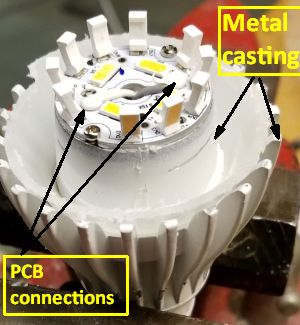
Finally, we’ll look at a dimmable bulb, one made by Feit Electric in China. Back in 2015, we also tore down a Feit bulb. This one is constructed quite a bit differently than the version we looked at four years ago. For starters, the older bulb carried 36 LEDs, some of them obscured by a weird
plastic shield. The new bulb has only 14 LEDs, though ten of them mount at an angle to the LED plate on a post-like support.
The old Feit bulb had several mechanical elements in common with the new model, including a plastic sleeve that holds the PCB and a big metal casting that seems to be a heat sink. But the old bulb loaded the PCB area with a rubber-like potting material which also provided structural support for the metal screw threads and bulb base.
On LED bulbs in 2015, it wasn’t uncommon to find the metal screw threads supported mainly by rubber-like potting material rather than by the bulb housing. The 2015 Feit bulb is a prime example. Its metal threads didn’t even touch the bulb housing. The potting material did all the work. Similarly, the base contact was separate from the metal screw threads. And electrical connections to the base and to the metal screw threads were via discrete wires.
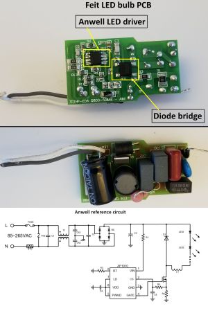
The new bulb has eliminated the potting material. It uses discrete wires to make connections to the mounting base and LED plate, as did the old bulb. But the wires seem to be machine-soldered and the solder connections to the LED plate are covered with what looks like a corrosion-resistant plastic material.
There are also big differences in the circuitry itself. The old bulb used a flyback converter chip from NXP. The new bulb uses a chip (AP1910) from Anwell Semiconductor in Taiwan. There aren’t a lot of details available about this device other than it is an open-loop peak current controller. The Feit bulb
is dimmable and the Anwell chip appears to be using a filtered version of the dimmer waveform to set the dimming level. The chip can also implement dimming via a PWM input, but there’s no sign of a PWM circuit for dimming on the Feit bulb. A final point to note is that the Feit bulb uses a separate power FET to control the LED current, so we can surmise the Anwell chip doesn’t incorporate one.
All in all, there’s been some progress in mechanical construction since we looked at LED bulbs four years ago. On the circuit side, it looks as though designers have concluded that even dimmable LED drivers don’t need to be complicated.

Fantastic article, I like my electronics simple and reliable, glad to know these are being made in a more automated fashion now!
simple does not always mean better.
And, I can not edit my previous comment….
I was curious if you can remake the FET circuit, where you put all the component values in the schematic, and also mention the name of the FET.
We provide the part number if we can find it, but sometimes the markings on the device package are ambiguous or there just aren’t any.
My friends apartment have ecosmart bulbs. Model # B7A19A60WESD34 9.5W 840Lumens 120V 5000K 101mA 60Hz made in china 1901. What do you recommend as a replacement bulb. That is better quality and will last longer.