• Skip to primary navigation
  • Skip to main content
  • Skip to primary sidebar
  • Skip to footer
  • Subscribe
  • Advertise

Power Electronic Tips

Power Electronic News, Editorial, Video and Resources

  • Products
    • Power Supplies
    • AC-DC
    • DC-DC
    • Battery Management
    • Capacitors
    • Magnetics
    • MOSFETS
    • Power Management
    • RF Power
    • Resistors
    • Transformers
    • Transistors
  • Applications
    • 5G
    • AI
    • Automotive
    • EV Engineering
    • LED Lighting
    • Industrial
    • IoT
    • Wireless
  • Learn
    • eBooks / Tech Tips
    • EE Training Days
    • FAQ
    • Learning Center
    • Tech Toolboxes
    • Webinars & Digital Events
  • Resources
    • Design Guide Library
    • Digital Issues
    • Engineering Diversity & Inclusion
    • LEAP Awards
    • Podcasts
    • White Papers
    • Design Fast
  • Video
    • EE Videos & Interviews
    • Teardown Videos
  • EE Forums
    • EDABoard.com
    • Electro-Tech-Online.com
  • Engineeering Training Days
  • Newsetter Subscription

Power Electronics Top Talks in May 2019 on EDABoard.com

June 2, 2019 By Aimee Kalnoskas

Peer-to-peer, engineer-to-engineer questions and answers from the EDABoard.com engineering community around power electronics. Click the “Read more” link and follow the entire conversation and maybe add your two cents by logging in to EDAboard.com

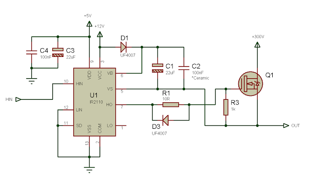
Problem with inverter’s drive – I tried to build this configuration but when I try to raise the voltage up to 12 volts the IC IR2110 (which drive (third switches) IGBT ) burn. Is the problem in the drive circuit? The drive circuit and the IGBT configuration is attached. Read more

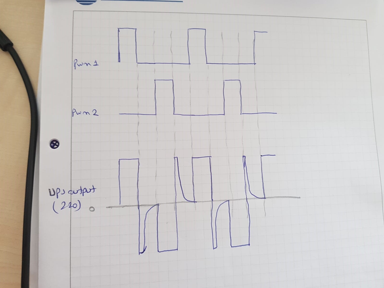
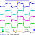
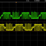
Inverter sinewave problem – I am trying to remake an inverter which previously designed with IPM. I redesign it with MOSFETs instead of IPM, and I use push-pull topology. I change the PWM pulse width while reading the input voltage of the inverter. Actually I think there is nothing wrong with PWM since if there is load at the output, there is no problem at all. But if there is no load at the output of inverter my sinewave is not as expected as you can see below. Read more

Parallel connection of multiple half-bridge – I want to build a 15Kw DC motor driver. Is it possible to design five 3Kw half-bridge motor driver and connect them in parallel? Read more

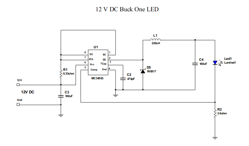
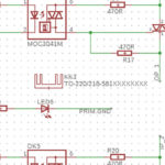
Controlling multiple power LED drivers – I have a couple of power LEDs, which I intend to control with an Arduino (not directly, with transistors), to achieve chase lights or other patterns. After trying different resistors, I gave up because of the heat problems. I found the following circuit in an ON Semiconductor application brief. Read more

SOA of MOSFET….the meaning of “DC” in the graph – In the graph of SOA in the SPB07N60C3 FET datasheet (pg 5), I presume the “DC” means “duty cycled,” or “Direct Current”…in other words “pulse trains” or continuous DC? Read more

Parallel connection of multiple LLC converters – I am trying to parallel 6 LLC converters each having their own synchronous rectification. Each converter has its own frequency control, so each has a different phase and amplitude with respect to each other. Each converter has its own closed loop voltage and current control. So a runaway of a single converter in the group is unlikely. Read more

Earthing and EMC of offline SMPS – Please could anyone elaborate on the meanings of various things in this (attached) document on Earthing & EMI Filters? The document is called “Safety concerns for practical EMI line filters“. Read more

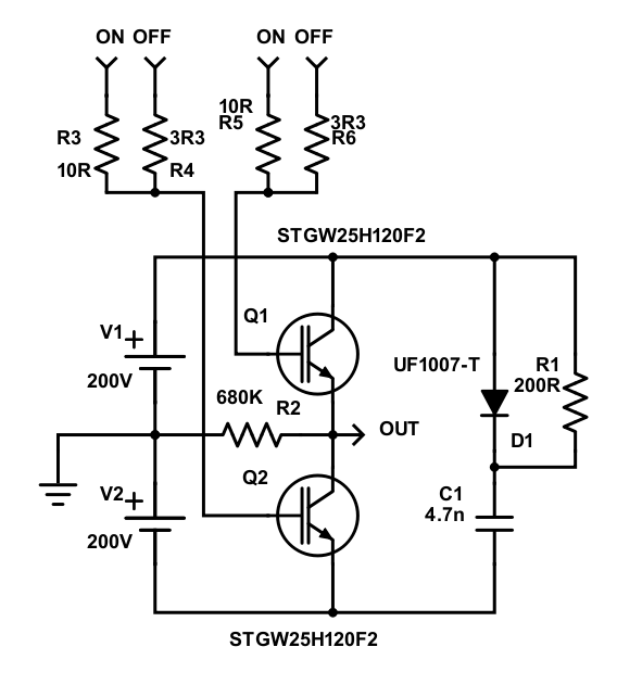
Unknown device in a high voltage chopper – I am curious to know what are the circled devices… Read more

Serious IGBT overshoot -I’m working on a power-supply but have run into some serious overshoot problems. As you can see I tried with an RCD snubber, but that didn’t change anything, do you perhaps have any suggestions on how to deal with this? Read more

H-bridge current spike – I’m simulating the following a class D amplifier as shown in the image. The PWM driving scheme is bipolar (25 kHz), the load is 20mH+1.9R, the driving resistors, and the dead time (250ns) correspond to those of the gate driver I choose. The actual transistor I’ll be using is the CSD18540Q5B, but as there is no open spice model of it, I’m simulating with the IPB090N06N3 which seems to be similar. The problem I find is that simulation shows a current spike on the lower transistor each time it turns on. Do you know where it might come from? Read more

You may also like:

  • power electronics
    Power Electronics Top Talks in April 2019 on EDABoard.com
  • power electronics
    Power Electronics Top Talks in March 2019 on EDABoard.com

  • Power Electronics Top Talks in February 2019 on EDABoard.com forums

  • Power Electronics Top Talks in January 2019 on EDABoard.com forums

Filed Under: Converters, Featured, LED Lighting, Transistors Tagged With: edaboardcom, infineontechnologiesinc

Primary Sidebar

Featured Contributions

Robust design for Variable Frequency Drives and starters

Meeting demand for hidden wearables via Schottky rectifiers

The case for vehicle 48 V power systems

GaN reliability milestones break through the silicon ceiling

Developing power architecture to support autonomous transportation

More Featured Contributions

EE LEARNING CENTER

EE Learning Center

EE TECH TOOLBOX

“ee
Tech Toolbox: 5G Technology
This Tech Toolbox covers the basics of 5G technology plus a story about how engineers designed and built a prototype DSL router mostly from old cellphone parts. Download this first 5G/wired/wireless communications Tech Toolbox to learn more!

EE ENGINEERING TRAINING DAYS

engineering
“power
EXPAND YOUR KNOWLEDGE AND STAY CONNECTED
Get the latest info on technologies, tools and strategies for EE professionals.
“bills

RSS Current EDABoard.com discussions

  • Mean offset increase in post-layout simulation of clocked comparator
  • problem connecting to my xilinx device VIA global IP
  • Testing 5kW Grid Tied inverter over 200-253VAC
  • Getting different output for op amp circuit
  • dc-dc converter in series

RSS Current Electro-Tech-Online.com Discussions

  • Back to the old BASIC days
  • using a RTC in SF basic
  • what's it's name
  • What is correct names for GOOD user friendly circuit drawing program?
  • Curved lines in PCB design

DesignFast

Component Selection Made Simple.

Try it Today
design fast globle

Footer

EE World Online Network

  • 5G Technology World
  • EE World Online
  • Engineers Garage
  • Analog IC Tips
  • Battery Power Tips
  • Connector Tips
  • DesignFast
  • EDA Board Forums
  • Electro Tech Online Forums
  • EV Engineering
  • Microcontroller Tips
  • Sensor Tips
  • Test and Measurement Tips

Power Electronic Tips

  • Subscribe to our newsletter
  • Advertise with us
  • Contact us
  • About us

Copyright © 2025 · WTWH Media LLC and its licensors. All rights reserved.
The material on this site may not be reproduced, distributed, transmitted, cached or otherwise used, except with the prior written permission of WTWH Media.

Privacy Policy