
Despite the contention that “everything is going digital,” amplifiers of analog signals have always been and continue to be important and unavoidable functions in real circuits and systems. Yet amplifiers which must produce significant output power from audio to RF face challenges of performance and efficiency. The industry has some long-established designations for classes of amplifiers which offer tradeoffs among key parameters, as well; as some relatively new classes. Part 1 looks at the older but still widely used classes commonly known as A, B, AB, C, and D.
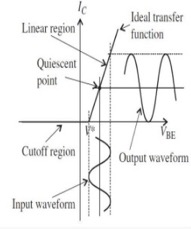
The Class A amplifier provides very high linearity and low distortion. Here, the active elements (originally vacuum tubes, now almost always transistors) are biased so their quiescent operating point is in the linear part of their conducting region, Figure 1. The input signal induces small-to-moderate excursions around this point, thus maintaining linearity of the input/output transfer function. The active amplifier element is always on and never cut off, regardless of the magnitude or polarity of the input, as the Class A amplifier has a 360⁰ conduction angle, meaning it is on and conducts throughout a full cycle of the input sine wave.
While a properly designed Class A amplifier is capable of excellent performance and was used for many years as the primary audio-amplifier topology, it has a major drawback in that it is inherently very inefficient (on the order of 20 to 30%). since it is always in the active region and so dissipates power even when there is no or just a small input signal. Largely for this reason, alternatives to Class A were devised.
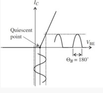
The Class B amplifier uses a “push-pull” arrangement with a pair of complementary amplifier elements (such as PNP/NPN transistors or N-/P-channel MOSFETs), each biased at cutoff with the conduction angle of each amplifier at 180⁰ (half cycle), Figure 2. When the bipolar, zero-centered input signal goes positive, one amplifier comes out of cutoff and goes into its active region, conducts, and amplifies; when the signal goes negative, the other amplifier does the same while the first one is cutoff and thus dissipating near-zero power.
The Class B amplifier can have efficiency in the 30-40% range, which is far better than Class A although still unacceptably high for many applications. Also, it suffers from crossover distortion which generates harmonics, which occurs as there is a slight lag or discontinuity as one active element turns on while the other turns off (and vice versa); ; distortion is typically between 10 and 20%. This may be acceptable for some situations but not for higher-quality audio designs.
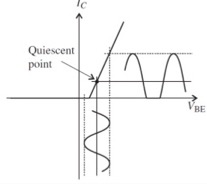
The Class AB amplifier is a blend of Class A and Class B, and strives to offer a compromise in efficiency and performance. In this topology, each of the pair of complementary active elements is biased slightly into the active region, and so there is some overlap between the two at the turn-on/turn-off center point, Figure 3. This reduces distortion to a low level – typically 1% and even down to 0.1% – at a slight increase in power dissipation. There is a tradeoff between conduction angle, which is somewhat greater than 180⁰, and resultant distortion, with increased conduction angle and associated dissipation yielding lower distortion. Until the development of advanced, digitally driven audio amplifiers, Class AB was the most commonly used audio amplifier approach.
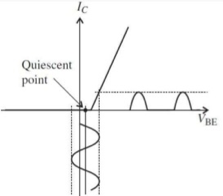
The Class C amplifier offers the highest efficiency, but has poor distortion characteristics and generates many undesired harmonics. In Class C, the amplifier conduction angle is far less than 180⁰, and it is biased so that it only turns on for large signal excursions. The output current and thus dissipation is zero for more than the one-half of the input signal, Figure 4.
The efficiency o f Class C amplifiers can be fairly high, up to about 70-80%, but since the distortion is also high (10 to 30%) the Class C approach cannot be used for audio. However, it is used for higher-power RF transmitters, where dissipation must be kept to acceptably low levels. To make the Class C amplifier usable, the undesired RF harmonics are removed by using a resonant output circuit as a low-pass filter.
The Class D amplifier (sometimes called a digital amplifier, though this is misleading) is a somewhat counterintuitive yet very effective topology. Instead of a linear or quasi-linear approach as with the other classes, it functions as a nonlinear, switching amplifier. The active element is either fully on or fully off, and is pulse-width modulated by the input signal, Figure 5. The output’s waveform is switched at a frequency which is far higher than the highest audio signal that needs to be amplified.
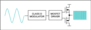
As a result of this fully on/off action, efficiency can approach 100%. The switching on/off output is low-pass filtered to restore the desired analog waveform shape with distortion of about 0.1% to 1%. Class D is now the dominant audio amplifier approach for PC audio cards, mobile devices, and automotive audio systems due to its attractive combination of performance, efficiency, and small size.
In the Part 2, we’ll look at Class G, H, and other classes of amplifiers.

[…] In Part 1, we looked at Class A, B, AB, C, and D amplifiers. These designations are standardized, fully defined, and widely recognized. Now we’ll look at a few other topologies which are less well known but also used. […]