
Thermistors can reliably switch in thermal protection to keep power electronics cool.
SONJA BROWN | EPCOS, A TDK GROUP CO.
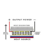
All semiconductors generate thermal losses, of course. Thermal losses in power semiconductors can range from a few watts to multiple kilowatts. In heatsinks, the conductive capability is typically measured in °K/W. The smaller the conductive capability value, the better the thermal dissipation capacity.
Three entities are necessary to determine the right heat sink for a power semiconductor: the thermal contact resistance, the maximum heat dissipation in the semiconductor, and the highest expected ambient temperature.
Some thermal dissipation happens by convection, but the limits of this method are quickly reached – especially with small chips that dissipate a lot of power. Consequently, it is impossible to guarantee – and not wise to rely on – convection cooling. Furthermore, heatsinks are often too big for compact designs. The best course of action is to actively dissipate heat via fans or combined air and water-cooled heat exchangers, which are often operated without regulation.
In many electronic power supplies and converters, power dissipation is load-related. To improve the energy balance and minimize the generation of noise, the active thermal dissipation switches on only when the electronics hits a defined temperature limit.
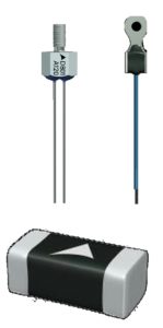
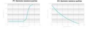
Thermistors are good candidates for detecting temperature limits. Thermistors can be positive temperature coefficient (PTC) or negative temperature coefficient (NTC) devices. With NTC thermistors, resistance falls with rising temperature. In PTC thermistors, the resistance increases as temperature drops. On exceeding a specific temperature, PTC thermistors show a sharp rise in resistance, making them useful as temperature limit sensors. NTC thermistors, on the other hand, exhibit greater linearity and are therefore suitable for temperature measurement.
Because of their steep temperature-resistance curves, PTC thermistors can monitor temperature limits and actuate a fan when the temperature is high enough. PTC thermistors can connect in series and, when functioning as temperature sensors, can monitor several hot spots. When a PTC sensor in a series connection exceeds the specified limit temperature, it switches the circuit to the high-ohmic state. For example, this action can be used in notebooks to monitor the main processor, the graphics processor, and any other heat-emitting components using SMD PTC sensors.
Another application of PTC sensors is in the thermal monitoring of motor windings. For example, some manufacturers offer special types of PTC sensors that can be easily integrated into the windings of three-phase motors.
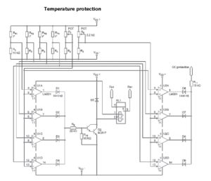
NTC thermistors can also be used for temperature monitoring – particularly when the linearity of their temperature-resistance characteristic comes in handy. For example, a high-performance audio end stage might use NTC sensors to detect two temperatures. In such a design, eight output transistors with emitter resistors can mount together on a cooling fan unit to minimize the housing dimensions. Four separate heatsinks might be arranged point-symmetrically to one another, with two power transistors on each heatsink.
Because the output transistors sit on four heatsinks that are both electrically and thermally insulated from one another, each heatsink must be monitored individually. This individual monitoring is necessary because even if the heat sinks are adequately dimensioned, the tolerances can result in a slightly uneven load distribution. The thermal monitoring must let the circuit take two actions: First, when one or more heatsinks reaches a temperature of 85°C, the fan must switch on. Second, a load must be shed upon reaching a temperature of about 100°C.
NTC sensors available from certain manufacturers are useful in scenarios where space is a constraint. They let a single NTC temperature sensor do the job rather than two sensors. The design outlined above lets the fan switch on reliably at 85 °C. As this design is relatively slow in thermal terms, there is no need to build in an on-off hysteresis circuit as would normally be the case.
References


Leave a Reply