• Skip to primary navigation
  • Skip to main content
  • Skip to primary sidebar
  • Skip to footer
  • Subscribe
  • Advertise

Power Electronic Tips

Power Electronic News, Editorial, Video and Resources

  • Products
    • Power Supplies
    • AC-DC
    • DC-DC
    • Battery Management
    • Capacitors
    • Magnetics
    • MOSFETS
    • Power Management
    • RF Power
    • Resistors
    • Transformers
    • Transistors
  • Applications
    • 5G
    • AI
    • Automotive
    • EV Engineering
    • LED Lighting
    • Industrial
    • IoT
    • Wireless
  • Learn
    • eBooks / Tech Tips
    • EE Training Days
    • FAQ
    • Learning Center
    • Tech Toolboxes
    • Webinars & Digital Events
  • Resources
    • Design Guide Library
    • Digital Issues
    • Engineering Diversity & Inclusion
    • LEAP Awards
    • Podcasts
    • White Papers
    • Design Fast
  • Video
    • EE Videos & Interviews
    • Teardown Videos
  • EE Forums
    • EDABoard.com
    • Electro-Tech-Online.com
  • Engineeering Training Days
  • Newsetter Subscription

Handling the 48-to-12-V stepdown

February 4, 2021 By Lee Teschler

A multiphase, interleaved buck converter can reduce bus voltage down to something useful in data center server racks.

Brad Xiao, Nazzareno (Reno) Rossetti Maxim Integrated

Hyperscale data centers that dissipate hundreds of megawatts demand efficient power delivery beyond the ability of the traditional 12-V power supplies on old server motherboards. A data center on 12 V has a power usage effectiveness (PUE) of 1.1 at best. It wastes 10% of its power (tens of megawatts) on cooling and overhead. That wasted power could comfortably supply electricity to a small city with about 10,000 homes.

server power architecture
Typical 48-V server architecture today powers low-voltage (< 1.8 V), high-current loads like memories and microprocessors via an unregulated 12-V rail. An open-loop, unregulated 4:1 switched tank converter (STC) produces the unregulated 12 V. (STCs use LC resonant tanks to partially replace flying—i.e. floating with respect to ground–capacitors for energy transfer. High-efficiency 12-V voltage-regulating converters power the various loads.

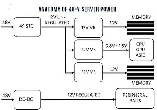
The move from 12 to 48-V power brings several advantages. The server rack dissipates heat more efficiently, costs less, and can be smaller as a consequence of the reduced current (4x), copper losses (16x), and connector/bus bar sizing. In the power management architecture of a modern data center, different strategies are adopted to power different classes of loads like processors, memories, and peripherals. Peripherals such as PCIE and HDDs require a 12-V supply rail. One way to get the required 12 V is through use of a multiphase, interleaved, coupled-inductor-based 48-to-12-V step-down converter. This converter design is compact, efficient, and cost-effective.

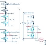
The best strategy to power low-voltage (< 1.8 V), high-current loads like memories and microprocessors is to reduce the 48 V down to an unregulated 12-V rail. An open-loop, unregulated 4:1 switched-tank converter (STC) topology enables soft-switching operation with peak efficiency in the 98% to 99% range. From here, high-efficiency 12-V voltage regulator-converters power the various loads. Peripherals like PCIE and HDDs require a 12-V supply rail and currents up to 100 A (1.2 kW). In this case, a 48-to-12-V regulated, interleaved, multiphase dc-dc converter can do the job.

four phase
A four-phase, coupled-inductor configuration yields an outstanding 97.9% peak and 97.43% full-load efficiency (12 V, 100 A, 1.2 kW) with the interleaved buck controller.

Use of a four-phase interleaved dc-dc converter reduces ripple current and, hence, ripple voltage, compared to that of a single-phase converter. Lowering output current ripple and voltage ripple means fewer capacitors on the output, resulting in a smaller BOM. The four-phase architecture also requires fewer input capacitors.

The total input current is the sum of the four out-of-phase currents. Here, spreading the total input current over time reduces the total RMS value of the input current compared to that of a single-phase setup. This spreading makes possible a smaller input current-ripple filter. Another great benefit of a four-phase converter is a fast transient response and lower voltage overshoot/undershoot during load steps. Lower overshoots, in turn, allow a tighter voltage rail powering the electronic load with less headroom needed for transient droop, resulting in less power dissipated at the load.

Additional efficiencies can be had through use of a coupled inductor in which the inductor coils wind around a common magnetic core. Here, the winding orientation is such that the magnetic flux cancels out, resulting in less than a quarter of the ripple current compared to that of four uncoupled inductors. Extremely low ripple current yields the smallest BOM and highest efficiency.

regulator
The 8-to-60-V MAX15157B fixed-frequency, accurate current report, current-mode PWM controller drives two power MOSFETs in this buck configuration, allowing OPERATION as a 48-to12-V step-down regulator. Click to enlarge.

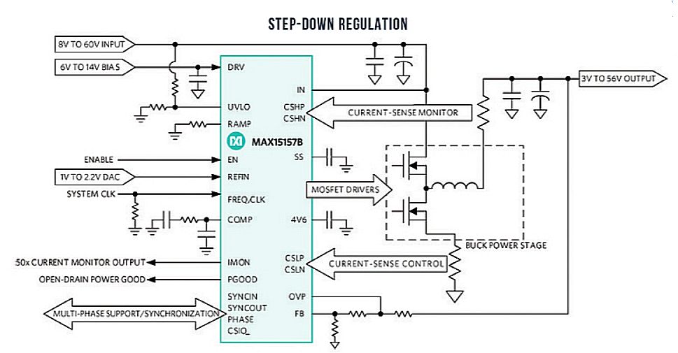
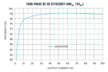
An example of a device that makes possible efficient 48-to-12-V conversion is the 8-to-60-V MAX15157B fixed-frequency, current-mode PWM controller. It drives two power MOSFETs in a buck configuration, synthesizing a 48-to-12-V step-down regulator. Four ICs–in conjunction with external discrete MOSFETs, capacitors, and a single coupled inductor–are interleaved for multi-phase operation. The switching frequency is controlled either through an external resistor setting the internal oscillator frequency or by synchronizing the regulator to an external clock. The device is designed to support switching frequencies ranging from 120 kHz to 1 MHz. Each IC is available in a 5×5-mm, 32-pin TQFN package and supports a -40 to +125°C junction temperature range. In a four-phase, coupled-inductor configuration, this topology yields an outstanding 97.9% peak and 97.43% full-load efficiency (12 V, 100 A, 1.2 kW).

48-to-12-V PCB
The 48-to-12-V PCB with a coupled inductor. The design easily fits on a motherboard. It fits in a quarter-brick footprint using one PCB side, in an eighth-brick footprint on two PCB sides.

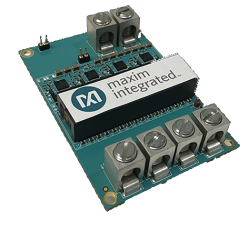
The 48-to-12-V PCB layout with a coupled inductor can easily sit on the data server motherboard. It fits in a quarter-brick size on one side of a PCB and in an eighth-brick form factor on two PCB sides.

In a nutshell, high levels of efficiency available through use of such 48-to-12-V conversion techniques offer a path toward power usage effectiveness approaching unity in a not-so-distant future.

You may also like:

  • acopian
    Picking reliable power supplies

  • Switched capacitor power conversion for electronic systems
  • sense-resistor
    Measuring a sense-resistor’s voltage drop, Part 2: Isolation
  • thermal management
    Thermal management considerations for board-mounted dc/dc converters
  • ac-line isolation
    The basics of AC-line isolation for safety, Part 1: The…

Filed Under: Controllers, Converters, FAQ, Featured, Power Electronics Handbook Tagged With: maximintegratedproductsinc

Primary Sidebar

Featured Contributions

Robust design for Variable Frequency Drives and starters

Meeting demand for hidden wearables via Schottky rectifiers

The case for vehicle 48 V power systems

GaN reliability milestones break through the silicon ceiling

Developing power architecture to support autonomous transportation

More Featured Contributions

EE LEARNING CENTER

EE Learning Center

EE TECH TOOLBOX

“ee
Tech Toolbox: Internet of Things
Explore practical strategies for minimizing attack surfaces, managing memory efficiently, and securing firmware. Download now to ensure your IoT implementations remain secure, efficient, and future-ready.

EE ENGINEERING TRAINING DAYS

engineering
“power
EXPAND YOUR KNOWLEDGE AND STAY CONNECTED
Get the latest info on technologies, tools and strategies for EE professionals.
“bills

RSS Current EDABoard.com discussions

  • Will this TL084C based current clamp circuit work?
  • Mains inverter with switching node going out on the mains cable!?
  • ISL8117 buck converter blowing up
  • MOSFET thermal noise in Weak vs Strong inversion
  • System verilog constraint error

RSS Current Electro-Tech-Online.com Discussions

  • Kawai KDP 80 Electronic Piano Dead
  • My Advanced Realistic Humanoid Robots Project
  • FSK SER on the same symbols
  • Wideband matching an electrically short bowtie antenna; 50 ohm, 434 MHz
  • using a RTC in SF basic

DesignFast

Component Selection Made Simple.

Try it Today
design fast globle

Footer

EE World Online Network

  • 5G Technology World
  • EE World Online
  • Engineers Garage
  • Analog IC Tips
  • Battery Power Tips
  • Connector Tips
  • DesignFast
  • EDA Board Forums
  • Electro Tech Online Forums
  • EV Engineering
  • Microcontroller Tips
  • Sensor Tips
  • Test and Measurement Tips

Power Electronic Tips

  • Subscribe to our newsletter
  • Advertise with us
  • Contact us
  • About us

Copyright © 2025 · WTWH Media LLC and its licensors. All rights reserved.
The material on this site may not be reproduced, distributed, transmitted, cached or otherwise used, except with the prior written permission of WTWH Media.

Privacy Policy