Switched capacitors (SCs) are highly-versatile circuit elements that can be used to provide various functions, ranging from micro-scale implementations embedded in integrated circuits (ICs) or designed into wearables and other small devices, to a variety of power conversion applications, up to grid-scale systems. This FAQ series will explore the versatility of switched-capacitors. Following this initial exploration of switched capacitor filters, amplifiers, integrators, and differentiators will be a dive into switched capacitors used in power conversion, including dc/dc converters, ac/dc power supplies, and solar inverters. The series will conclude with a look at “Emerging applications for switched capacitor power conversion,” including electric vehicles, grid-scale power conversion, and various possibilities for combining SC converters with state-of-the-art gallium-nitride (GaN) power switches to provide advanced power conversion solutions.
The SC resistor is the most basic SC implementation. It consists of a single capacitor and two switches, which alternatively connect the SC to the input and output in a non-overlapping manner. Because the two switches’ switching frequency controls the charge transfer, the SC looks like a resistor with a value dependent on the capacitance and switching frequency. SC resistors are used to replace simple resistors in ICs because they are easier to fabricate with a variety of values, and the final value can be fine-tuned by changing the switching frequency.
SC resistors are programmable via the clock frequency changes since the resistance is equal to the inverse of the capacitance multiplied by the clock frequency (1/C * f). Consider the example: C = 5pF and f = 100kHz, which results in a resistance equivalent to 2MΩ, a very high resistance value from a small capacitor. With a conventional approach, a large area of silicon would be needed to produce an equivalent resistance. In addition to the size consideration, the tolerance of resistance would be up to 50%, reducing the circuit’s accuracy.

When embedded in ICs, SC circuits are typically implemented using CMOS technology and are composed of MOS capacitors combined with MOSFET switches. Typical CMOS SC circuits applications include mixed-signal integrated circuits, digital-to-analog converter chips, analog-to-digital converter circuits, and pulse-code modulation (PCM) codec-filters, and PCM digital communications. One of the basic building blocks is the SC filter.
SC filters
SC resistors can be combined with conventional capacitors to produce low-pass filters. The presence of switched capacitors to replace the resistor(s) within filters, both passive and active (using op amps), enables filters as fully integrated circuits.
SC filters are accurate and efficient. Any error in an absolute value of a parameter can reach up to 30% (tolerance), while the resulting error of ratio of capacitance values can be as low as 0.1%. And, replacing resistors reduces dissipated power. SC low-pass filter cut-off frequency characteristics and considerations include:
- The cut-off frequency is dependent on the ratio between two capacitance values, not the absolute values
- The ratio of the capacitance in an IC structure can typically be kept within a tolerance of 0.1%, and any temperature dependence of the capacitors affects both devices equally and does not change the capacitance ratio
- The cut-off frequency is tunable by varying the clock frequency that switches the MOSFETs on and off, thereby adjusting the filter’s corner frequency
- Using an accurate and stable clock is important when designing SC filters

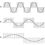
As a result of their switching characteristics, SC filters are a form of sampled data system and must conform to the Nyquist criteria to eliminate any possibility of aliasing on the output (the device must operate at over 2X the highest frequency present on the input). In a typical SC filter implementation, the operating frequency is over 50x the input signal bandwidth, providing a guard band to avoid aliasing. Aliasing only becomes a concern for low-frequency applications, which can be handled with the addition of a second low-pass filter pole.
Disadvantages of SC filters compared to active RC filters can include more noise and a phenomenon called clock feedthrough, where clock artifacts feed through to the filter output and cause noise and/or distortion.
SC amplifiers
A basic SC fixed-gain amplifier consists of an op-amp, an input capacitor (CA), a feedback capacitor (CF), and five switches. (see image below) There are two phases of operation: Phase Φ1 is referred to as charge transfer phase, with the charge acquired by the input capacitor transferred to output. Phase Φ2 is referred to as the signal acquisition phase, during which the input capacitor acquires the input signal.

The opamp’s offset voltage, added to both capacitors, removes the possible effect the offset may have on the output during the charge transfer phase. It’s called an “autozero” adjustment.
During a brief transition time between the two phases, all the switches are open to prevent failure of the circuit. During this “dead band” the stored charge on the capacitors does not change. During Phase 2 (Φ2), the input capacitor’s charge will take the only available path: through the feedback capacitor. Therefore, the feedback capacitor receives the same charge transfer. The result is an inverting amplifier with a gain set by the ratio of its two capacitors. The output voltage is only correct at the end of phase 2, and it will be near ground (at the offset voltage) during phase 2. Therefore, the sampling of SC circuit outputs must be properly timed.

Comparators, integrators, and differentiators
Removal of the feedback capacitor in the non-inverting amplifier described above results in a SC comparator. Eliminating the capacitor from the feedback loop sets the capacitor value to zero. Since the amplifier’s gain in the above circuit is the ratio of the two capacitors, removal of the feedback capacitor results in infinite gain, and the amplifier becomes a comparator. In the circuit below, during phase 1, the capacitor is charged with the input voltage. During phase 2, Vout is low if Vin is greater than analog ground (AGND), and Vout is high if Vin is less than AGND.

SCs and opamps can also be used to build integrators and differentiators. Removing the switch from CF to ground in the inverting amplifier maintains the charge on CF during the acquisition phase 1 while still allowing transfer of the input charge. During phase 1, the input capacitor (CF) charges to the input voltage, and CF maintains its charge. During phase 2, Ca discharges through CF, transferring its charge to CF. This circuit is an adjustable integrator. The gain can be changed by changing the capacitor ratios or by adjusting the sampling frequency.

A differentiator results when the input capacitor is hard connected to the analog input. In this circuit, the feedback capacitor acts like a resistor, and the input capacitor is used as a series capacitor. During phase 1, the input capacitor acquires the input voltage at that moment, Vin(T), and the feedback capacitor is discharged. During phase 2, if the input voltage changes by Δ, the charge on the input capacitor changes by Δ * CA. That same amount of charge is transferred to CF, resulting in a voltage across the feedback capacitor of Δ*CA/CF and the output voltage is proportional to the change in the input voltage over time. This is an adjustable gain differentiator with the gain equal to the ratio CA/CF.

As shown, switched capacitors are highly versatile. They can be used to implement variable resistors and filters. When paired with opamps, it can be used to build a wide variety of useful circuit blocks. The second FAQ in this series will consider the use of SCs in power conversion, including dc/dc converters, ac/dc power supplies, and solar inverters. The series will conclude with a look at “Emerging applications for switched capacitor power conversion,” including grid-scale power conversion and various possibilities for combining SC converters with state-of-the-art gallium-nitride (GaN) power switches to provide advanced power conversion solutions.
References
Switched capacitor, Wikipedia
The switched capacitor, Analog Devices
Understanding PSoC1 Switched Capacitor Analog Blocks, Cypress Semiconductor


Leave a Reply