
Electrolytic capacitors have a reputation for failing spectacularly when mistreated.
Leland Teschler • Executive Editor
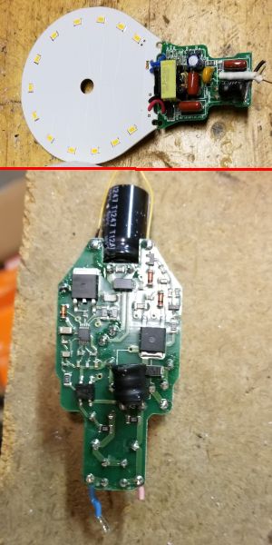
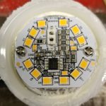
Pop open a common LED bulb and you’ll often find an electrolytic capacitor occupying a place in the input from the ac line. Though illumination-grade LEDs generally have lifetimes exceeding 10,000 hours, the electrolytic caps in their base may not last nearly that long. There may be a variety of reasons for such bad outcomes.
Perhaps the main reason for difficulties with electrolytic caps is their poor performance when exposed to reverse voltages. Electrolytics are polarized devices that only work well when applied signals on the cap’s positive terminal exceed that on the negative terminal. The sensitivity to polarity arises because of the cap’s construction.
The most common electrolytic cap is the aluminum electrolytic. Its anode electrode (+) is a pure aluminum foil with an etched surface. A thin insulating layer of aluminum oxide acts as the dielectric of the capacitor. A non-solid electrolyte covers the rough surface of the oxide layer, serving in principle as the cathode (-). A second aluminum foil called “cathode foil” touches the electrolyte and serves as the electrical connection to the cathode. The entire assembly is rolled up to form the distinctive cylindrical shape defining electrolytics.
A point to note is that applying a positive voltage to the anode material in the electrolytic bath forms an insulating aluminum oxide layer. Its thickness corresponds to the applied voltage. This oxide layer acts as the dielectric. After forming a dielectric oxide on the rough anode structures, a counter-electrode must match the rough insulating oxide surface. The electrolyte serves this purpose.
The thickness of the dielectric is thin, typically measured in nanometers. The voltage strength of the oxide layer is quite high in the right direction. But exceeding the maximum voltage spec can make the capacitor look like an electrical short. The result can make for a noteworthy video as evidenced by the number of exploding capacitors available for viewing on YouTube.
Here’s where polarity comes in: Applying a signal with the wrong polarity prevents the oxide layer from forming. The result, again, can be catastrophic failure.
Of course, application circuits that are functioning properly will supply signals of the right polarity to the electrolytic caps they use. The most common culprit for shortening electrolytic cap life is heat. A capacitor rated for 10,000 h at 25°C will be derated for use in higher temperatures–it may only be rated for 1,000 h at 85°C, even less at 105°C. The heat generally acts to evaporate the electrolyte and reduce the capacitance. Additionally, an electrolytic cap can heat up when it is in a circuit that repeatedly and rapidly charges and discharges it. And performance changes caused by high temperatures are temporary, Spec-sheet performance will reappear once the capacitor returns to a normal temperature (assuming it hasn’t been damaged by over-temperature). There are capacitors rated for long life at higher temperatures for when temperature is a problem.
Another notorious factor for shortening electrolytic cap life is the ripple current the cap sees. Ripple current is common in power regulator circuits that frequently employ electrolytic caps. For complex electrochemical reasons, the higher the ripple current, the greater and faster the cap degrades. Sensitivity to ripple current is a function of the cap construction and materials. Vendors specify operating life with different ripple-current values. Additionally, there are electrolytic caps designed specifically to handle high-ripple current.
Unfortunately, supply chain issues can also impact cap performance. Substandard or outright counterfeit parts are increasingly common in procurement channels. It is relatively easy to make an adequate capacitor that will function acceptably in the short term. However, operating life can easily be substandard.
For example, the capacitance of even high-quality electrolytic capacitors can drift from the nominal value over time. It is not unusual to large tolerances specified, typically 20%. Thus an aluminum electrolytic capacitor with a nominal capacitance of 47 µF can be expected to measure anywhere between 37.6 µF and 56.4 µF. Tantalum electrolytic capacitors can have tighter tolerances, but typically have lower operating voltages. And all bets are off with regard to the tolerance over time of substandard or counterfeit caps.
It also pays to know the conditions under which cap spec sheet ratings apply. Rated capacitance is generally indicated as the value at 20°C and 120 Hz. The capacitance will be reduced at temperatures higher and lower than 20°C. Note, too, the spec for loss tangent. The loss tangent is defined as the tangent of the difference of the phase angle between capacitor voltage and capacitor current with respect to the theoretical 90° value. The difference is caused by the dielectric losses within the capacitor. The tangent of the loss angle (tan δ) is indicated as the value at 20°C and 120 Hz. This value will drop at higher temperatures and rise at lower temperatures.
Additionally, both capacitance and tangent of the loss angle differ with frequency. Capacitance is lower at high frequencies, and tangent of the loss angle is higher at high frequencies. Capacitor impedance is generally expressed as the value at 20°C and 100 kHz. The impedance will be higher at lower frequencies.
Storage conditions can also affect electrolytic cap performance. The leakage current in an aluminum electrolytic capacitor will rise if the capacitor is stored for extended periods. As with other capacitor parameters, the effect is more pronounced at higher storage temperatures. However, applying a voltage can reduce the leakage current . This is the principle behind reconditioning an electrolytic capacitor by applying a voltage. The the same reason, circuit designers should consider the initial increases in cap current when designing the equipment. The usual technique is to put a guard circuit in parallel with the cap.

The packaging of the cap itself can cause problems. Note there is no isolation between the capacitor case and the cathode terminal. Manufacturers typically don’t specify the amount of resistance between the electrolytic capacitor case and the cathode terminal. The cap outer sleeves are also susceptible to damage. The sleeve may crack if exposed to high temperatures. Generally the outer sleeves are made from PVC, but the PVC is there for labeling, not to provide electrical insulation. Electrolytic caps typically also incorporate pressure vents that take the form of a thin area on the outer case, put there to handle pressure build-up if the cap is mistreated. It’s good to figure out where the vent is and allow a space above it.
Finally, slight differences in capacitors wired in series or parallel can lead to issues. For example, electrical current may not balance evenly among capacitors in parallel. In power supplies, one outcome can be excessive ripple current one or more of the caps. Similarly, when two or more capacitors connect in series, the balance of the applied voltages must be taken into account so the voltages applied to each of the individual capacitors stay below the rated voltages. The usual approach is to install voltage divider resistors in parallel with each of the capacitors.


I’ve replaced many an electrolytic cap and even a few tantalums. The first was a power supply for a monitor. Doing so gave it a few more years of life. Next was an old VHS/DVD recorder, still in use today. A few tantalum caps failed on a 25-year-old HP34401A multimeter. The caps were in the 18 V supply used for AC measurements. The failure was so bad that it burned the PCB pads. One pad went to ground and I had to add a wire from the end of the cap to the nearest ground pad.
This explains how the ceiling fan start capacitor reduces in value over time because of the heat generated by fan winding and proximity of the electrolytic capacitor.