
Three top power-integrity engineers explain why you must consider the complete power system. Looking at just the power supply is not nearly enough.

“There’s a hard divide between power integrity and power electronics,” said Picotest’s Steve Sandler. What is he talking about, you might ask?
Sandler, along with Keysight’s Heidi Barnes and Signal Edge Solutions’ Benjamin Dannan will present the seminar, How Power Integrity is Changing the World of Power Electronics, on Sunday, March 19 at the 2023 APEC conference in Orlando. EE World spoke with Sandler, Barnes, and Dannan about this divide and how they plan to educate engineers at APEC.

The divide between power integrity and power electronics, according to Sandler, arises because power-supply designers look at the power-supply design. Unfortunately, you must look at your design with both the power supply and load in mind. Sandler argues that power-electronics engineers don’t necessarily understand what the power supply contributes to the system.

Power integrity — the fidelity of power on a board and at a chip — has become an issue with high-speed digital signals. When a transmitter of a digital signal sends a bit, it needs more power for a short period of time. Power supplies simply can’t deliver that instantaneous power, which is why a board needs decoupling capacitors — sometimes lots of them — located close to the load. The problem stems from board impedance and inrush current, which causes power loss when a signal changes state and a chip needs additional power.
Sandler noted that chips used for AI and high-performance computers can draw 1000 A to 2000 A for a single device. At such a high current, parasitic inductance can wreak havoc on a board’s power rail. “In a supercomputer,” noted Sandler, “you need upwards of 1000 decoupling capacitors to compensate for just 20 pH [the thickness of a sheet of paper in PCB trace length] of parasitic inductance.”
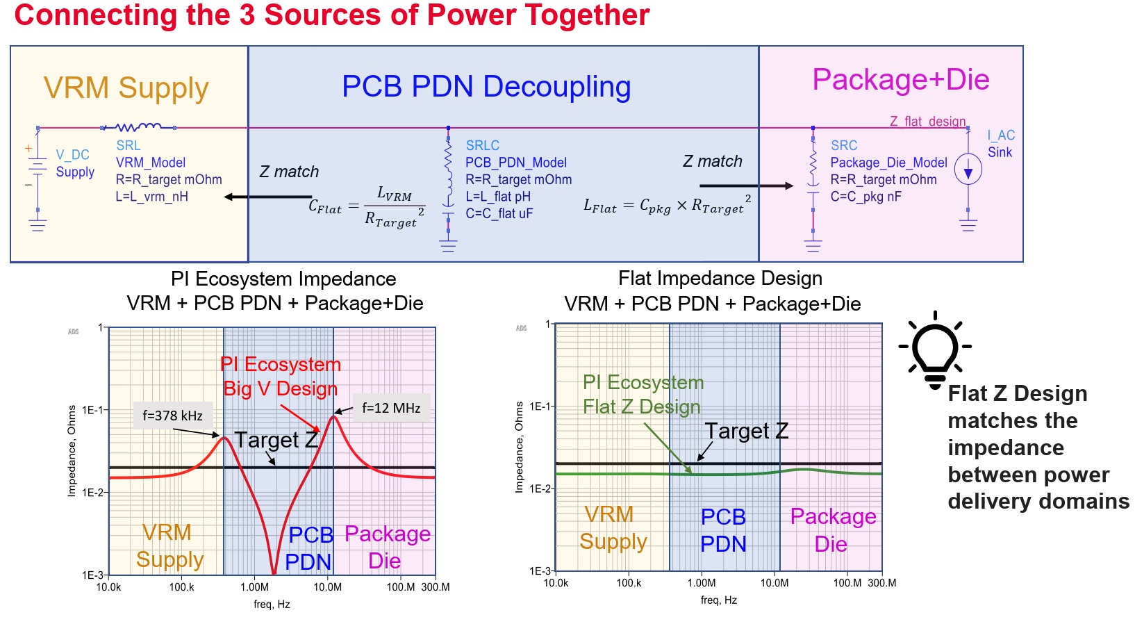
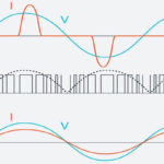
Barnes looks at power integrity from an RF perspective; after all, the rise times of digital signals contain frequencies into the microwave range and beyond. “In the microwave world, you want matched impedances from source to transmission line to load [Figure 1]. It’s not about achieving the lowest board impedance as some power-electronics engineers might think, it’s about matched impedance. At 2000 A, you will see even the effects of the smallest parasitic impedance, things you might think matter only at gigahertz frequencies.”
“To achieve matched impedances,” continued Barnes, “you need to simulate the entire system, including the board’s parasitic inductance.” Sandler noted that power-supply and voltage-regulator module (VRM) designers often don’t take that into account. Even if they do run simulations, Sandler argued that they look for free or low-cost simulation tools. “People don’t think they need to simulate these parasitics even though power sources have to supply power to fast-changing circuits. Board parasitics are important to simulate as part of the entire system.”
Measurements matter
In the end, you want to simulate a system and, once you have the hardware, measure its performance. “Power engineers think they just need an oscilloscope, test leads, and hookup wire,” said Sandler. He argued that engineers working on boards with high-speed data links need to measure the effects of those signals on power rails. That means you need equipment that can accurately measure those effects at the frequencies they contain. If you’re working on boards with 800 Gb/sec PAM4 serial links, you need equipment that can handle the frequencies involved. Sandler said that power-supply designers think a 4-GHz oscilloscope is sufficient. “Of course, you’ll think there’s no problem because you can’t see it.”
What will you learn from the seminar? The session will open with an introduction to power integrity for power-electronics engineers. It will cover how a power supply fits into an overall system. This portion of the seminar will delve into how VRMs work, then look at what’s between a VRM and its load, typically an ASIC.
You’ll also learn what information you need to perform a simulation and what component manufacturers might not tell you. What does the power look like at the ASIC? What is decoupling? “You need to look at inductance, and that’s a struggle for power-supply engineers to understand,” said Sandler. You’ll learn how the amount of decoupling capacitance you need for a given load relates to a board’s parasitic inductance. According to Sandler, it all comes down to one equation:
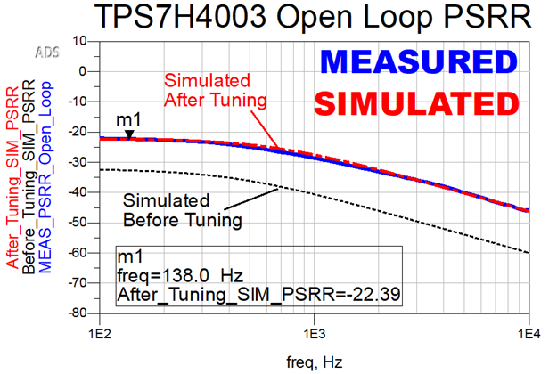
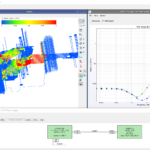
Dannan will show, step-by-step, the process of how to build an actual measurement-based voltage-regulator module (VRM) model based on the Sandler State-Space Average Model (SSAM) in Keysight PathWave ADS. This includes details on the necessary measurements, how to tune the model to get high-fidelity results, and how to troubleshoot your simulation when it doesn’t match your measurement (Figure 2). He will show how, based on the SSAM VRM model, a VRM matches (or correlates) to measurements. Engineers will see in this session that even the ringing in the simulation is perfectly in line with the measurement. Lastly, as part of his session, Dannan will show an analysis of why you can’t use passive SPICE models for VRMs and how there is over 47 dB greater difference in the noise spectrum when using the SSAM versus a fitted passive SPICE VRM model with PCB effects.
Heidi Barnes is a 2017 recipient of the DesignCon Engineer of the Year award. Sandler received the same honor at DesignCon 2023.
New paper on Power Integrity Requirements From AEi Systems
A New Power Integrity Requirement to Supplement Target Impedance: Quantifying PDN Impedance Flatness from Sandler NISM
by Scott Witcher, Steve Sandler
Target impedance is the most common power distribution network (PDN) design requirement used in industry today, but it is fundamentally limited because it does not account for PDN voltages responses to different input current waveforms, and it can only predict worst-case voltage excursions in the specific case of a flat PDN impedance profile. Since no impedance path is perfectly flat, and PDNs inevitably contain one or more resonances which can generate worst-case voltage excursions, it is critical to quantify whether PDN impedances are “flat enough”. This presentation demonstrates a methodology to quantify PDN impedance flatness using quality factor, group delay, and Sandler Non-Invasive Stability Measurement (NISM), and also proposes a PDN impedance flatness requirement to supplement target impedance requirements.
Contact info@aeng.com for more information.